NdFeB cutting kerf loss reduction is the process of minimizing the material removed as sawdust during magnet slicing — directly converting wasted rare earth material into additional finished magnets from the same sintered block. For every 0.1 mm you reduce kerf width, you gain 2–4 extra slices per block depending on target thickness, which translates directly to lower material cost per piece.
With NdFeB raw material representing the largest single cost in magnet manufacturing, cutting kerf loss is not a minor process detail — it is the highest-leverage parameter for reducing per-piece cost without changing material grade, magnet design, or supplier.
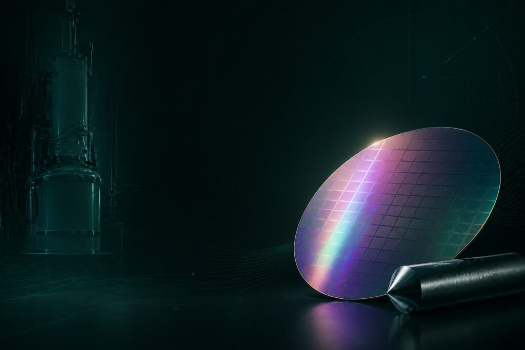
Why NdFeB Cutting Kerf Loss Reduction Matters
Sintered NdFeB contains neodymium, praseodymium, dysprosium, and other rare earth elements whose prices have risen significantly. According to Trading Economics, neodymium prices have shown sustained upward pressure driven by EV motor demand and supply-side constraints. Unlike steel or aluminum, rare earth material lost as cutting dust cannot be economically recycled in most factory settings — the contamination from coolant, wire abrasive, and mixed alloy grades makes reclamation impractical at production scale.
This means every milligram of kerf dust is a direct cost write-off.
Consider a typical production scenario: slicing a 50 × 50 × 30 mm NdFeB block into 2 mm thick magnets. With a conventional ID (inner diameter) saw producing 0.55 mm kerf, you get approximately 11 finished slices. Switch to a diamond wire process achieving 0.28 mm kerf, and the same block yields 14 slices — a 27% increase in output from identical raw material input.
Across an annual production volume of 100,000 blocks, that difference compounds into tens of thousands of additional finished magnets with zero additional material purchase. This is why NdFeB cutting kerf loss reduction has become the primary process optimization focus for cost-conscious magnet manufacturers.
5 Parameters That Control NdFeB Cutting Kerf Loss
NdFeB cutting kerf loss reduction depends on five interdependent process parameters. Adjusting one parameter without considering its effect on the others typically trades kerf improvement for surface quality degradation or wire breakage. The table below summarizes each parameter’s role and optimal range based on published research.
| Parameter | Effect on Kerf | Recommended Range | Risk if Out of Range |
|---|---|---|---|
| Wire Diameter | Primary kerf determinant — kerf width ≈ wire diameter + 20–50 μm | 0.20–0.35 mm | Thinner wire = higher breakage risk |
| Wire Tension | Controls wire deflection during cut; lower deflection = straighter kerf | 15–25 N (single wire) | Over-tension → wire snap; under-tension → wavy cut |
| Feed Rate | Determines cutting force and heat generation | 0.1–1.0 mm/min | Too fast → chipping + wider effective kerf |
| Cutting Fluid | Removes swarf, reduces friction, controls thermal expansion | Water-based, 5–8% concentration | Insufficient flow → thermal kerf widening |
| Wire Speed | Controls abrasive engagement frequency and heat distribution | 800–1,600 m/min | Too slow → localized overheating |
Research published in Micromachines (MDPI) confirmed that feed rate and wire speed are the two most statistically significant parameters affecting surface quality during NdFeB diamond wire sawing, with optimal results achieved at feed rates below 0.4 mm/min combined with wire speeds above 1,200 m/min.
Parameter 1: Wire Diameter — The Primary Kerf Driver
Wire diameter is the single most impactful factor in NdFeB cutting kerf loss reduction because kerf width cannot be smaller than the wire itself. The relationship is direct: kerf width equals wire diameter plus the diamond abrasive overhang on both sides (typically 10–25 μm per side).
| Wire Type | Wire Diameter | Typical Kerf Width | Relative Material Loss |
|---|---|---|---|
| ID Saw Blade | 0.40–0.60 mm (blade thickness) | 0.50–0.70 mm | Baseline (100%) |
| Standard Diamond Wire | 0.30–0.35 mm | 0.35–0.42 mm | 50–60% |
| Fine Diamond Wire | 0.20–0.25 mm | 0.25–0.30 mm | 35–45% |
| Ultra-Fine Multi-Wire | 0.10–0.12 mm | 0.13–0.16 mm | 20–25% |
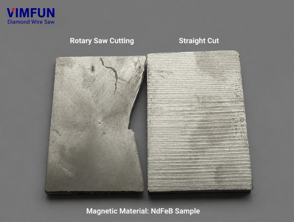
Switching from an ID saw blade to a 0.25 mm diamond wire reduces kerf loss by approximately 50–60%. This is the single largest improvement available and should be the first step in any NdFeB cutting kerf loss reduction program.
However, thinner wire requires corresponding adjustments to tension, feed rate, and cutting fluid parameters. A 0.20 mm wire run at parameters optimized for a 0.35 mm wire will break within minutes. The parameter interdependency means wire diameter selection must drive all downstream parameter choices.
Parameter 2: Wire Tension — Controlling Deflection
Wire tension directly controls how much the wire deflects under cutting force. Excessive deflection widens the effective kerf beyond the wire’s physical diameter because the wire follows a curved path through the workpiece rather than a straight line.
For NdFeB cutting kerf loss reduction, the target is to maintain wire deflection below 50 μm across the full cutting length. The required tension depends on wire diameter and span length:
- 0.30–0.35 mm wire: 20–25 N tension, supporting up to 50 mm cutting length
- 0.20–0.25 mm wire: 12–18 N tension, supporting up to 40 mm cutting length
- Multi-wire systems: Individual wire tension controlled by roller alignment and dancer systems
Under-tensioned wire produces wavy surfaces with effective kerf widths 30–50% wider than the theoretical minimum. Over-tensioned wire risks sudden fracture, which damages the workpiece and requires re-threading — a more costly outcome than the marginal kerf improvement.
Parameter 3: Feed Rate — The Speed vs. Quality Tradeoff
Feed rate controls how quickly the wire advances through the NdFeB block. Faster feed rates increase cutting force, which increases wire deflection, abrasive wear rate, and thermal load — all of which widen the effective kerf.
Research from Materials (MDPI) demonstrated that surface roughness increased approximately 3× when feed rate was raised from 0.1 mm/min to 0.3 mm/min during NdFeB diamond wire sawing, with corresponding increases in lateral wire swing amplitude.
For NdFeB cutting kerf loss reduction, the practical feed rate guidelines are:
- Precision slicing (0.1–0.3 mm/min): Minimum kerf, best surface quality (Ra < 0.5 μm), lowest throughput
- Production slicing (0.3–0.7 mm/min): Balanced kerf and throughput, surface roughness Ra 0.5–2.0 μm
- High-volume slicing (0.7–1.3 mm/min): Maximum throughput, wider kerf, requires post-processing lapping
The optimal feed rate for most NdFeB production applications falls between 0.3–0.5 mm/min, where kerf width remains within 15% of the theoretical minimum while maintaining economically viable throughput.
Parameter 4: Cutting Fluid — Thermal and Mechanical Control
Cutting fluid serves three functions in NdFeB cutting kerf loss reduction: removing swarf from the cutting zone, reducing friction between wire and workpiece, and controlling thermal expansion of both wire and magnet.
NdFeB is particularly sensitive to thermal effects during cutting. The material’s low thermal conductivity (7.7 W/m·K) means cutting heat concentrates at the contact zone rather than dissipating through the workpiece. This localized heating causes thermal expansion of both the wire and the NdFeB material, temporarily widening the kerf beyond what mechanical parameters alone would produce.
Water-based cutting fluids at 5–8% concentration provide the best combination of cooling performance and lubricity for NdFeB slicing. Key specifications:
- Flow rate: 2–5 L/min per cutting zone, directed at wire entry point
- Temperature: Maintain fluid below 25°C — use a chiller for continuous production
- Filtration: 10 μm or finer to remove NdFeB particles that would accelerate wire wear
- pH control: 8.5–9.5 to prevent NdFeB corrosion (NdFeB oxidizes rapidly in acidic conditions)
Insufficient cutting fluid is the most common cause of unexpected kerf widening in otherwise well-configured systems. If kerf measurements consistently exceed the expected wire diameter + 40 μm, check fluid flow rate and nozzle alignment before adjusting other parameters.
Parameter 5: Wire Speed — Abrasive Engagement Optimization
Wire speed determines how many diamond abrasive grains contact the NdFeB material per unit time. Higher wire speed distributes the cutting load across more abrasive points, reducing the force per grain and producing a smoother, narrower kerf.
The tested range of 800–1,600 m/min shows clear improvement in both surface quality and kerf consistency at higher speeds. At 1,600 m/min with a 0.22 mm wire, researchers achieved surface roughness Ra of 0.433 μm — approaching lapped surface quality directly from the saw.
However, wire speed has diminishing returns above approximately 1,400 m/min for most NdFeB grades. The practical limitations are:
- Machine vibration: Higher speed amplifies any imbalance in guide rollers
- Coolant delivery: Fluid must penetrate the cutting zone despite air entrainment at high wire speeds
- Wire wear rate: Faster speed means faster abrasive depletion, requiring more frequent wire replacement
For production-scale NdFeB cutting kerf loss reduction, wire speeds of 1,000–1,400 m/min provide the best balance of kerf quality and consumable cost.
NdFeB Cutting Kerf Loss Reduction: Before and After Comparison
The following table summarizes realistic improvements achievable by systematically optimizing all five parameters, based on a typical factory upgrading from ID saw to diamond wire processing for a NdFeB cutting machine setup:
| Metric | Before (ID Saw) | After (Optimized Diamond Wire) | Improvement |
|---|---|---|---|
| Kerf Width | 0.55 mm | 0.27 mm | 51% reduction |
| Slices per 30 mm Block (2 mm target) | 11 | 14 | +27% yield |
| Surface Roughness Ra | 1.5–3.0 μm | 0.4–0.8 μm | 2–4× better |
| Edge Chipping Rate | 8–12% | < 2% | Significant reduction |
| Post-cut Lapping Required | Always | Often eliminated | Process step saved |
These improvements compound across production volume. A facility processing 500 blocks/day at the improved yield gains approximately 1,500 additional finished magnets daily — without purchasing additional raw material.
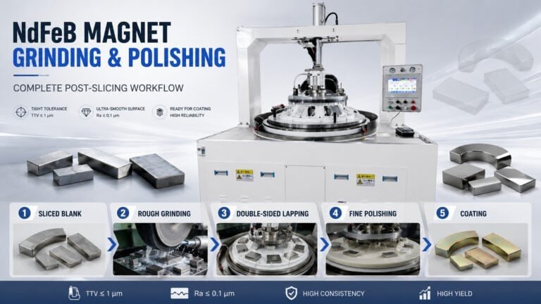
When combined with matched downstream equipment in a magnet production line equipment configuration, the kerf-optimized slicing output feeds directly into grinding and polishing stages without intermediate rework, further reducing per-piece cost.
How to Start Your NdFeB Cutting Kerf Loss Reduction Program
Implementing NdFeB cutting kerf loss reduction does not require replacing your entire production line simultaneously. A practical starting sequence:
Step 1: Measure your current baseline. Record kerf width, slices per block, and scrap rate for your current process across 50–100 blocks. You cannot improve what you have not measured.
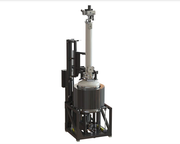
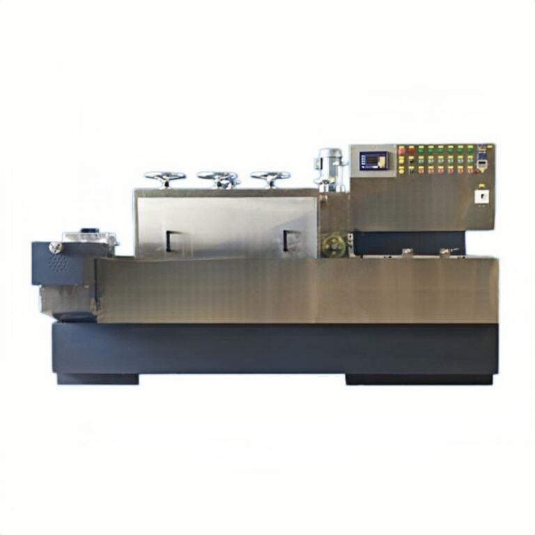
Step 2: Evaluate wire diameter options. If you are currently using an ID saw, the switch to diamond wire slicing on a dedicated NdFeB cutting machine provides the largest single improvement. If already using diamond wire, test one diameter step finer (e.g., 0.30 mm → 0.25 mm) with correspondingly adjusted tension and feed rate.
Step 3: Optimize cutting fluid system. Upgrade filtration to 10 μm, add temperature control, and verify nozzle alignment delivers fluid to the wire entry point — not above or beside it.
Step 4: Run parameter trials. Test 3–5 feed rate / wire speed combinations at your new wire diameter. Measure kerf width, surface roughness, and wire life for each combination. Select the parameter set that minimizes kerf while maintaining acceptable throughput and wire consumption cost.
Step 5: Scale and monitor. Implement the optimized parameters across production. Track kerf width weekly — wire supplier changes, NdFeB grade variations, and seasonal temperature fluctuations can shift your optimal parameters.
For EV motor magnet manufacturing applications where dimensional consistency directly affects motor performance, kerf optimization becomes even more critical: tighter kerf control means tighter thickness tolerance, which means fewer rejects at the motor assembly line.
Ready to quantify the material savings available from your specific NdFeB cutting process? Request a Free Process Optimization Audit →
Our engineering team will analyze your current cutting parameters, magnet geometry, and production volume to calculate the projected kerf reduction and material cost savings — with specific equipment and parameter recommendations for your facility.