NdFeB切断時のカーフ損失低減とは、磁石のスライス中に発生する鋸屑として除去される材料を最小限に抑えるプロセスであり、無駄になった希土類材料を同じ焼結ブロックから追加の完成磁石に直接変換します。カーフ幅を0.1mm短縮するごとに、目標厚さにもよりますが、ブロックあたり2〜4枚の追加スライスが得られ、これは1個あたりの材料コストの直接的な削減につながります。.
NdFeB原材料は磁石製造における最大の単一コストを占めるため、切断カーフ損失はマイナーなプロセス詳細ではなく、材料グレード、磁石設計、またはサプライヤーを変更せずに、1個あたりのコストを削減するための最もレバレッジの高いパラメータです。.
NdFeB切断カーフ損失低減が重要な理由
焼結NdFeBには、価格が大幅に上昇したネオジム、プラセオジム、ジスプロシウムなどの希土類元素が含まれています。 Trading Economics, によると、ネオジム価格はEVモーターの需要と供給側の制約によって持続的な上昇圧力を示しています。鋼やアルミニウムとは異なり、切断粉塵として失われた希土類材料は、ほとんどの工場環境では経済的にリサイクルできません。冷却剤、ワイヤー研磨材、および混合合金グレードからの汚染により、生産規模での回収は非現実的です。.
これは、カーフダストのミリグラム単位が直接的なコストオフであることを意味します。.
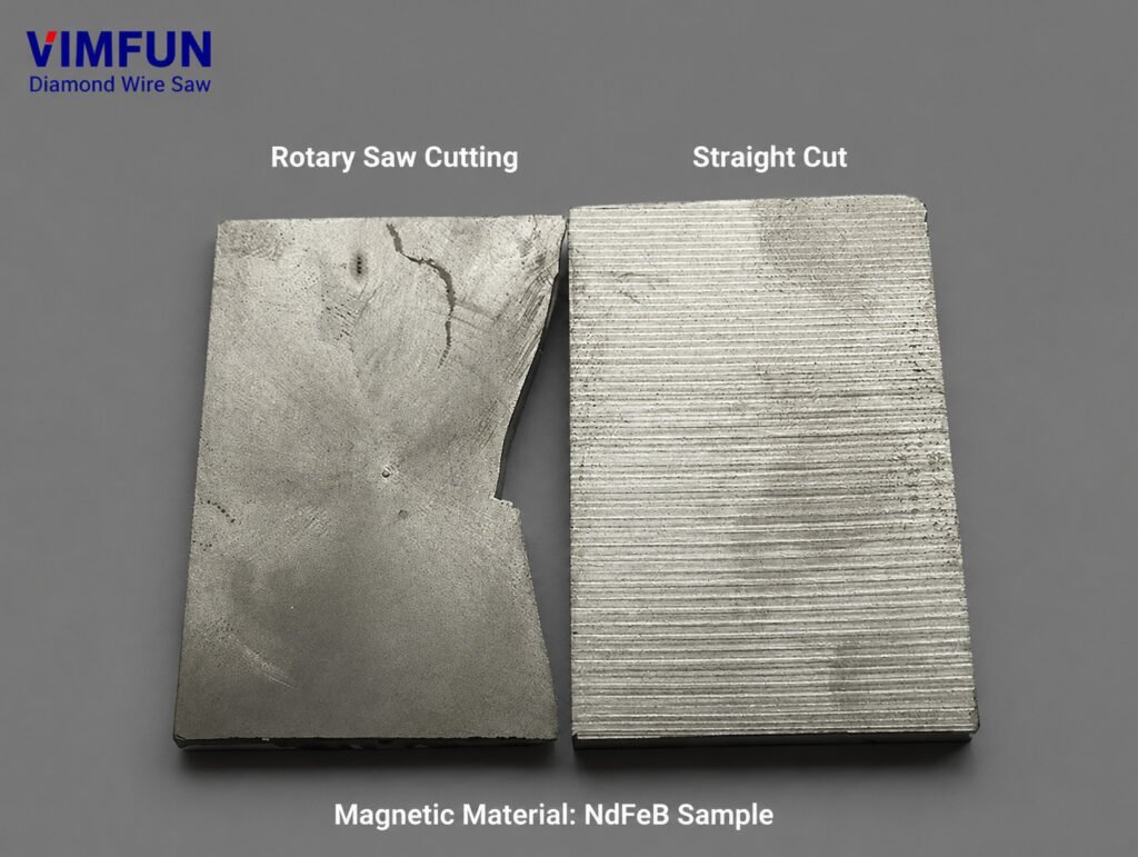
標準的な生産シナリオを考えてみましょう。50 x 50 x 30 mmのNdFeBブロックを厚さ2 mmの磁石にスライスします。従来のID(内径)ソーで0.55 mmのカーフを発生させると、約11枚の完成スライスが得られます。カーフ幅0.28 mmを達成するダイヤモンドワイヤープロセスに切り替えると、同じブロックから14枚のスライスが得られます。これは、同じ原材料入力から生産量が271%増加したことになります。.
年間100,000ブロックの生産量全体で、この差は、追加の材料購入なしで数万個の追加の完成磁石に積み重なります。これが、NdFeB切断カーフ損失低減がコスト意識の高い磁石メーカーにとって主要なプロセス最適化の焦点となっている理由です。.
NdFeB切断カーフ損失を制御する5つのパラメータ
NdFeB切断カーフ損失低減は、5つの相互依存的なプロセスパラメータに依存します。1つのパラメータを他のパラメータへの影響を考慮せずに調整すると、通常はカーフの改善と引き換えに表面品質の低下やワイヤーの破損が発生します。以下の表は、公開された研究に基づいた各パラメータの役割と最適な範囲をまとめたものです。.
| パラメータ | カーフへの影響 | 推奨範囲 | 範囲外の場合のリスク |
|---|---|---|---|
| ワイヤー径 | 主要なカーフ決定要因 — カーフ幅 ≈ ワイヤー直径 + 20–50 μm | 0.20–0.35 mm | 細いワイヤー = 破損リスクが高い |
| ワイヤーテンション | カット中のワイヤーたわみを制御します。たわみが低いほど、カーフはまっすぐになります。 | 15~25 N(シングルワイヤー) | 過度の張力 → ワイヤー切れ。張力が不足 → 波打ったカット |
| 送り速度 | 切削力と発熱を決定します。 | 0.1~1.0 mm/min | 速すぎる → チッピング + 有効カーフ幅の拡大 |
| 切削液 | スラッジを除去し、摩擦を減らし、熱膨張を制御します。 | 水性、5~8%濃度 | フロー不足 → 熱によるカーフ幅の拡大 |
| ワイヤースピード | 研磨材の係合頻度と熱分布を制御します。 | 800~1,600 m/min | 遅すぎる → 局所的な過熱 |
で発表された研究 Micromachines (MDPI) は、NdFeBダイヤモンドワイヤーソーイングにおける表面品質に最も統計的に有意な影響を与える2つのパラメータは送り速度とワイヤー速度であり、最適な結果は送り速度0.4 mm/min未満とワイヤー速度1,200 m/min以上を組み合わせた場合に達成されることを確認しました。.
パラメータ1:ワイヤ径 — 主要なカーフドライバ
ワイヤ径は、NdFeB切断カーフ損失低減において最も影響力の大きい要因です。なぜなら、カーフ幅はワイヤ自体よりも小さくすることはできないからです。関係は直接的です。カーフ幅は、ワイヤ径に両側のダイヤモンド研磨材のオーバーハング(通常、片側あたり10〜25μm)を加えたものに等しくなります。.
| ワイヤータイプ | ワイヤー径 | 標準的なカーフ幅 | 相対材料損失 |
|---|---|---|---|
| IDソーブレード | 0.40–0.60 mm(ブレード厚) | 0.50–0.70 mm | ベースライン(100%) |
| 標準ダイヤモンドワイヤ | 0.30〜0.35 mm | 0.35–0.42 mm | 50–60% |
| ファインダイヤモンドワイヤ | 0.20–0.25 mm | 0.25–0.30 mm | 35–45% |
| 超ファインマルチワイヤ | 0.10–0.12 mm | 0.13–0.16 mm | 20–25% |
IDソーブレードから0.25 mmのダイヤモンドワイヤーに切り替えることで、カーフロスは約50〜60%削減されます。これは利用可能な最大の改善であり、NdFeB切断カーフロス削減プログラムの最初のステップとなるはずです。.
ただし、細いワイヤーは、張力、送り速度、切削液のパラメータに対応する調整が必要です。0.35 mmワイヤー用に最適化されたパラメータで実行された0.20 mmワイヤーは、数分以内に破損します。パラメータの相互依存性により、ワイヤー径の選択がすべての下流のパラメータ選択を推進する必要があります。.
パラメータ2:ワイヤー張力 — たわみの制御
ワイヤー張力は、切削力下でのワイヤーのたわみ量を直接制御します。過度のたわみは、ワイヤーがワークピースを直線ではなく曲線経路で通過するため、ワイヤーの物理的直径を超えて実効カーフを広げます。.
NdFeB切断カーフロス削減では、目標は切断長全体でワイヤーのたわみを50 μm未満に維持することです。必要な張力は、ワイヤー径とスパン長に依存します。
- 0.30–0.35 mmワイヤー:20〜25 Nの張力で、最大50 mmの切断長をサポート
- 0.20–0.25 mmワイヤー:12〜18 Nの張力で、最大40 mmの切断長をサポート
- マルチワイヤーシステム:ローラーの配置とダンサーシステムによって制御される個別のワイヤー張力
張力が不足したワイヤーは、理論上の最小値よりも30〜50%広い実効カーフ幅を持つ波状の表面を生成します。張力が過剰なワイヤーは突然の破損のリスクがあり、ワークピースを損傷し、再スレッドが必要になります。これは、わずかなカーフ改善よりもコストのかかる結果です。.
パラメータ3:送り速度 — スピード対品質のトレードオフ
送り速度は、ワイヤーがNdFeBブロックを通過する速度を制御します。送り速度が速いほど、切削力が増加し、ワイヤーのたわみ、研磨材の摩耗率、熱負荷が増加します。これらすべてが実効カーフを広げます。.
研究によると 材料 (MDPI) NdFeBダイヤモンドワイヤーソーイングにおいて、送り速度を0.1 mm/minから0.3 mm/minに上げた際に表面粗さが約3倍になり、それに伴って横方向のワイヤー振幅も増加することが実証されました。.
NdFeBの切り込み損失低減のため、実用的な送り速度の目安は以下の通りです。
- 精密スライス (0.1–0.3 mm/min): 切り込み幅最小、表面品質最高 (Ra < 0.5 μm)、スループット最低
- 生産スライス (0.3–0.7 mm/min): 切り込み幅とスループットのバランス、表面粗さ Ra 0.5–2.0 μm
- 大量生産スライス (0.7–1.3 mm/min): スループット最大、切り込み幅広め、後工程でのラップ加工が必要
ほとんどのNdFeB生産用途において最適な送り速度は0.3–0.5 mm/minの間であり、この範囲では切り込み幅は理論上の最小値の15%内に収まり、経済的に実行可能なスループットを維持できます。.
パラメータ4:切削液 — 熱的および機械的制御
切削液は、NdFeBの切り込み損失低減において、切削ゾーンからの切りくず除去、ワイヤーとワークピース間の摩擦低減、ワイヤーとマグネット双方の熱膨張制御という3つの機能を提供します。.
NdFeBは、切削中の熱的影響に特に敏感です。材料の熱伝導率が低い (7.7 W/m·K) ため、切削熱はワークピース全体に拡散するのではなく、接触ゾーンに集中します。この局所的な加熱は、ワイヤーとNdFeB材料双方の熱膨張を引き起こし、機械的パラメータだけでは生じる以上の切り込み幅を一時的に広げます。.
濃度5–8%の水系切削液は、NdFeBスライスにおいて冷却性能と潤滑性の最良の組み合わせを提供します。主な仕様:
- 流速: 2~5 L/min(切削ゾーンあたり)、ワイヤ挿入口に向けた
- 温度: 作動液を25℃未満に保つ — 連続生産にはチラーを使用する
- ろ過: 10 μm以下、ワイヤ摩耗を加速させるNdFeB粒子を除去するため
- pH制御: 8.5~9.5、NdFeBの腐食を防ぐ(NdFeBは酸性条件下で急速に酸化する)
切削液の不足は、その他の設定が良好なシステムで予期せぬカーフ幅の拡大が生じる最も一般的な原因です。カーフ測定値が常に予想されるワイヤ径+40μmを超える場合は、他のパラメータを調整する前に、作動液流量とノズルアライメントを確認してください。.
パラメータ5:ワイヤ速度 — 研磨材の食い込み最適化
ワイヤ速度は、単位時間あたりにNdFeB材料に接触するダイヤモンド研磨粒子の数を決定します。ワイヤ速度が高いほど、切削負荷がより多くの研磨ポイントに分散され、粒子あたりの力が減少し、より滑らかで狭いカーフが得られます。.
試験された800~1,600 m/minの範囲では、高速化により表面品質とカーフの一貫性の両方で明確な改善が見られました。0.22 mmのワイヤで1,600 m/minの場合、研究者は表面粗さRa 0.433 μmを達成しました — これは、ソーから直接ラップされた表面品質に近づいています。.
ただし、ほとんどのNdFeBグレードでは、ワイヤ速度は約1,400 m/minを超えると収穫逓減します。実用的な制限は次のとおりです。
- 機械の振動: 高速化は、ガイドローラーのいかなる不均衡も増幅します
- クーラント供給: 高速ワイヤ速度での空気巻き込みにもかかわらず、作動液は切削ゾーンに浸透する必要があります
- ワイヤー摩耗率より高速な速度は、研磨材の消耗を早め、より頻繁なワイヤー交換が必要になることを意味します。
生産規模のNdFeB切断におけるカーフ損失削減においては、ワイヤー速度1,000〜1,400 m/minが、カーフ品質と消耗品コストの最適なバランスを提供します。.
NdFeB切断におけるカーフ損失削減:比較(変更前と変更後)
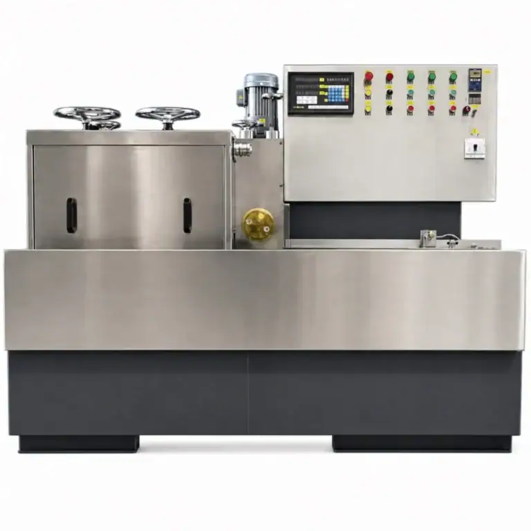
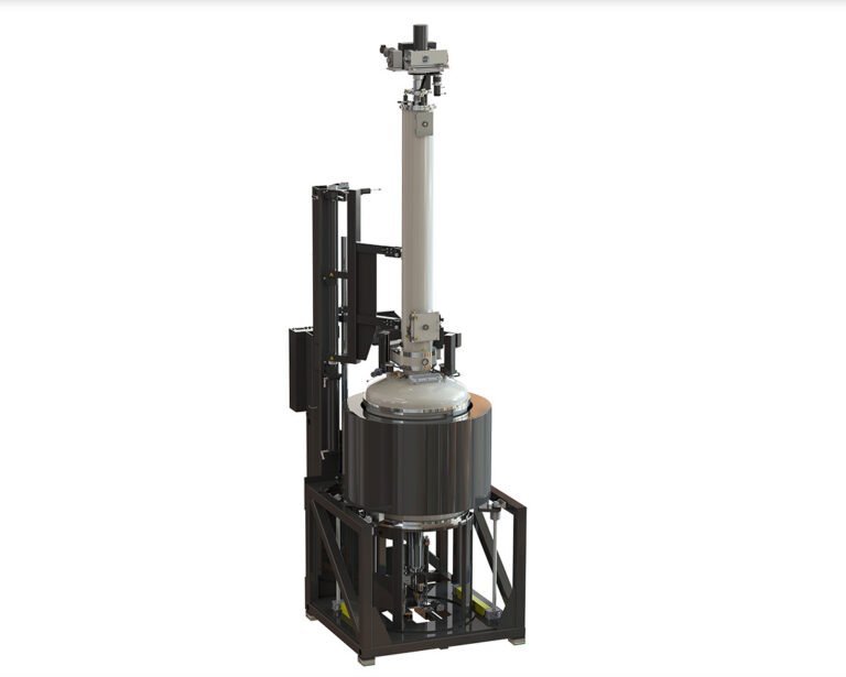
次の表は、IDソーからダイヤモンドワイヤー加工へのアップグレードを行う典型的な工場に基づき、5つのパラメータすべてを体系的に最適化することで達成可能な現実的な改善点をまとめたものです。 NdFeB切断機 セットアップ:
| メトリック | 変更前(IDソー) | 変更後(最適化されたダイヤモンドワイヤー) | 改善 |
|---|---|---|---|
| 切り口幅 | 0.55 mm | 0.27 mm | 51%削減 |
| スライス数/30 mmブロック(目標2 mm) | 11 | 14 | +27%収量 |
| 表面粗さ Ra | 1.5–3.0 μm | 0.4–0.8 μm | 2〜4倍向上 |
| エッジチッピング率 | 8–12% | < 2% | 大幅な削減 |
| カット後のラップが必要 | 常に | しばしば不要になる | 工程ステップの削減 |
これらの改善は生産量全体で複利効果を生みます。1日あたり500ブロックを処理する施設では、歩留まりが改善されることで、追加の原材料を購入することなく、1日あたり約1,500個の完成磁石が増加します。.
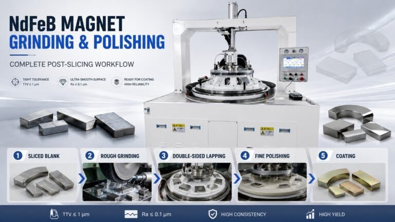
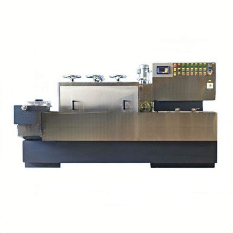
マッチングされた下流機器と組み合わせた場合、 磁石生産ライン機器 設定では、カーフ最適化されたスライス出力は、中間的な手直しなしで研削および研磨ステージに直接供給され、ピースあたりのコストをさらに削減します。.
NdFeB切断カーフ損失削減プログラムを開始する方法
NdFeB切断カーフ損失削減の実施は、生産ライン全体を同時に交換する必要はありません。実践的な開始順序:
ステップ1:現在のベースラインを測定します。. 現在のプロセスで、50〜100ブロックにわたるカーフ幅、ブロックあたりのスライス数、およびスクラップ率を記録します。測定していないものを改善することはできません。.
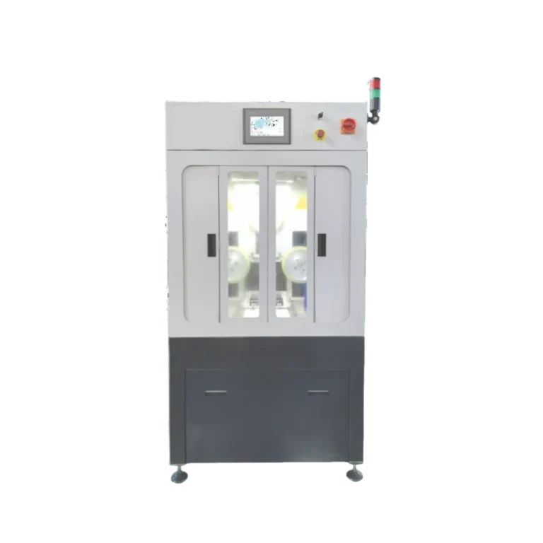
ステップ2:ワイヤ径のオプションを評価します。. 現在IDソーを使用している場合、専用のダイヤモンドワイヤスライシングへの切り替えは、 NdFeB切断機 単一の最大の改善を提供します。すでにダイヤモンドワイヤを使用している場合は、ワイヤ径を1段階細く(例:0.30 mm → 0.25 mm)し、それに伴って張力と送り速度を調整してテストしてください。.
Step 3: Optimize cutting fluid system. Upgrade filtration to 10 μm, add temperature control, and verify nozzle alignment delivers fluid to the wire entry point — not above or beside it.
Step 4: Run parameter trials. Test 3–5 feed rate / wire speed combinations at your new wire diameter. Measure kerf width, surface roughness, and wire life for each combination. Select the parameter set that minimizes kerf while maintaining acceptable throughput and wire consumption cost.
Step 5: Scale and monitor. Implement the optimized parameters across production. Track kerf width weekly — wire supplier changes, NdFeB grade variations, and seasonal temperature fluctuations can shift your optimal parameters.
について EV motor magnet manufacturing applications where dimensional consistency directly affects motor performance, kerf optimization becomes even more critical: tighter kerf control means tighter thickness tolerance, which means fewer rejects at the motor assembly line.
Ready to quantify the material savings available from your specific NdFeB cutting process? Request a Free Process Optimization Audit →
Our engineering team will analyze your current cutting parameters, magnet geometry, and production volume to calculate the projected kerf reduction and material cost savings — with specific equipment and parameter recommendations for your facility.