Kerf and material use
A parallel wire web makes multiple cuts in one feed. Actual kerf depends on the wire and cutting conditions; wire diameter alone is not the measured material loss.
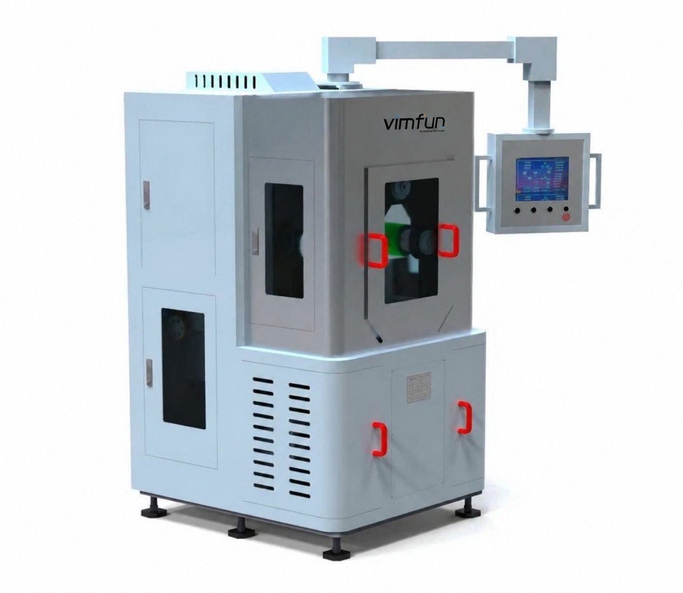
From blank to a qualified slicing process. Match your material, part geometry and inspection requirements to the right SOM configuration.
Discuss your partCompare models10 SOM models · 6 application groups · Free sample cutting
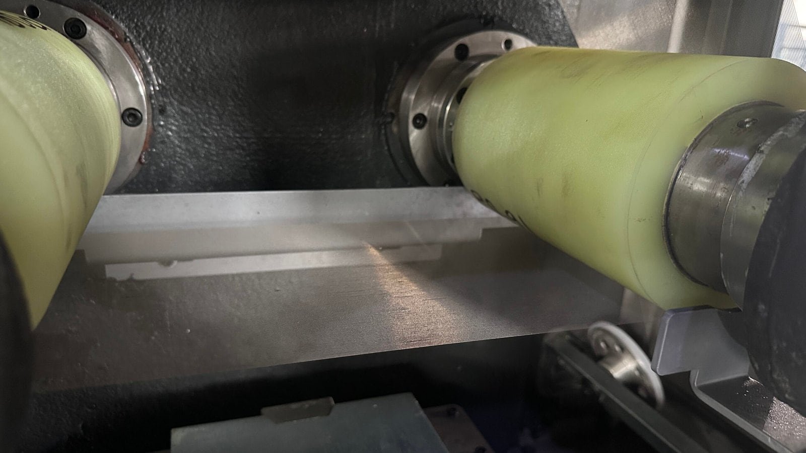
A parallel wire web makes multiple cuts in one feed. Actual kerf depends on the wire and cutting conditions; wire diameter alone is not the measured material loss.
Wire pitch and actual kerf determine the as-cut slice thickness. Allow separately for grinding or polishing before specifying the finished dimension.
Review support, fixture clearance and release of the slices. Assess edge chipping and surface condition on your material before fixing the production settings.
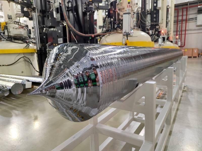
Crop and prepare the ingot to suit the machine envelope before loading.
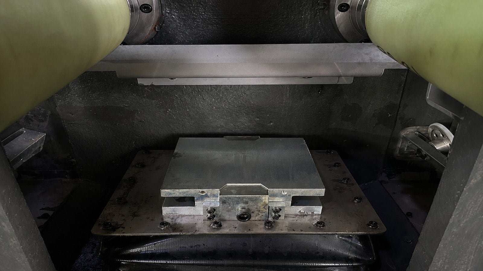
SOM200 fixture before loading. Review support and clearance for the prepared blank.
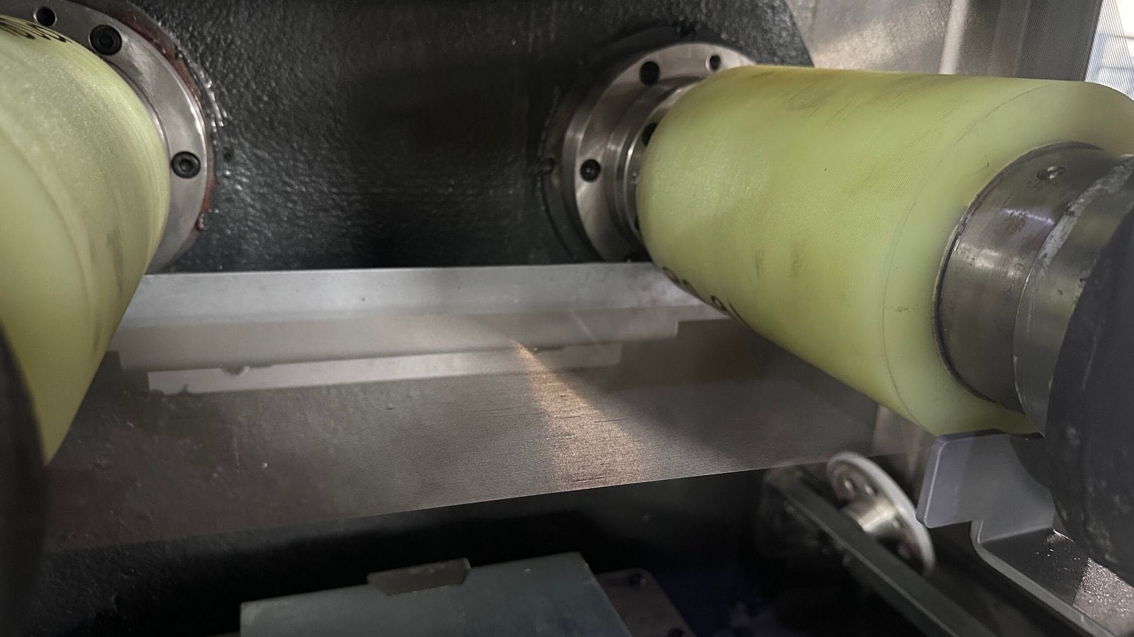
Parallel wire web and guide rollers. Set the cutting conditions for the material and slice requirement.
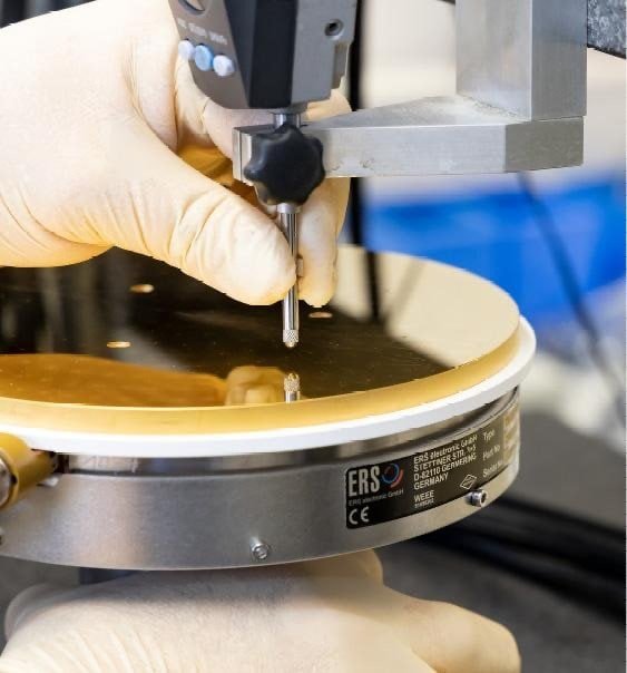
Contact-probe inspection. Agree the measurement method and acceptance criteria for your part.
Images illustrate the individual stages; they do not document a single workpiece or one continuous production run.
Start with the workpiece and cutting route. Then compare the listed envelope and slice range with your fixture and finishing requirements.
A compact option for small batches, frequent material changes and process development. Start here when a full production machine would exceed the workpiece and batch requirements.
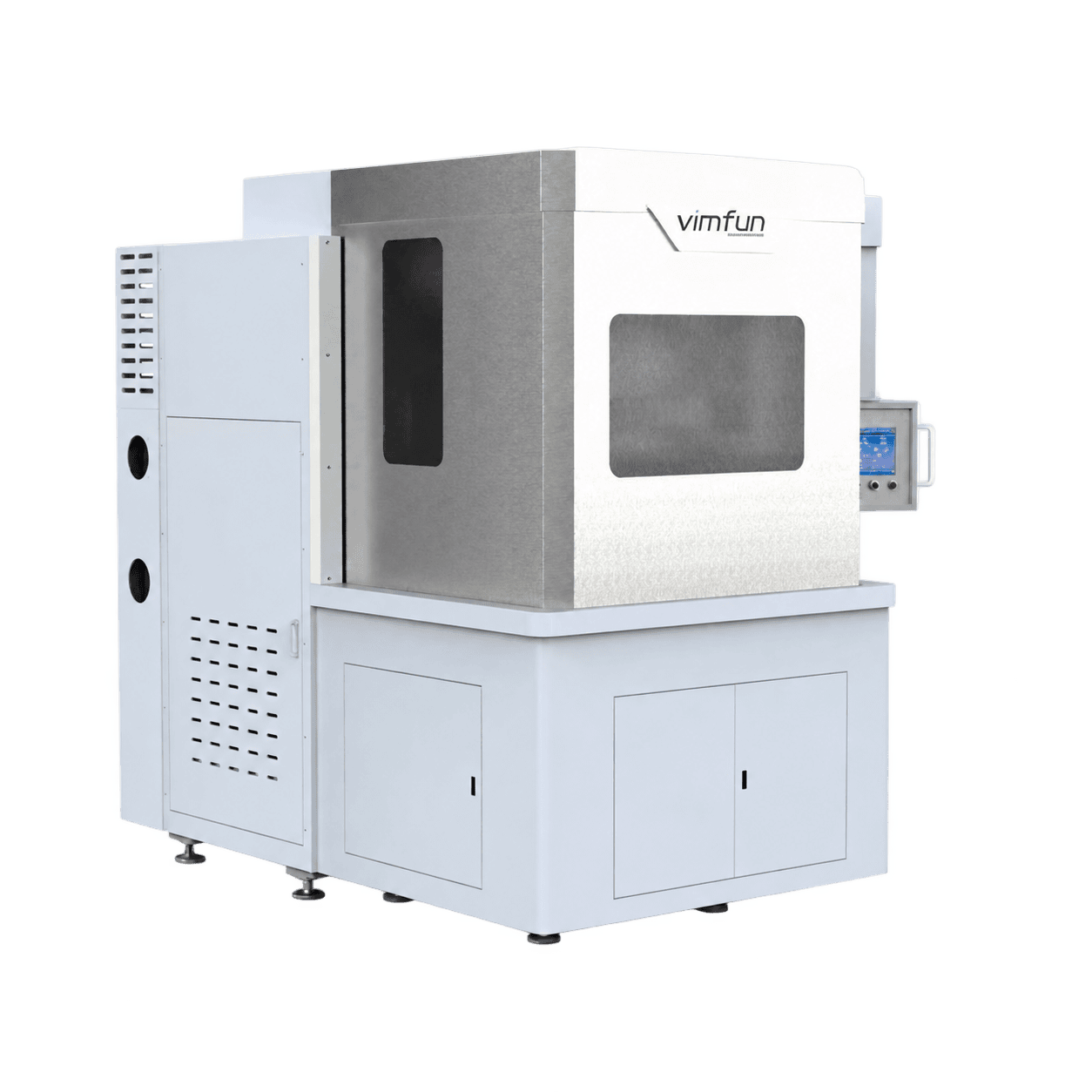
Prioritize this model when the workpiece cross-section is the constraint. Its dual work-plate arrangement differs from simply extending the length of a narrow billet. Review the two-plate layout with your fixture.
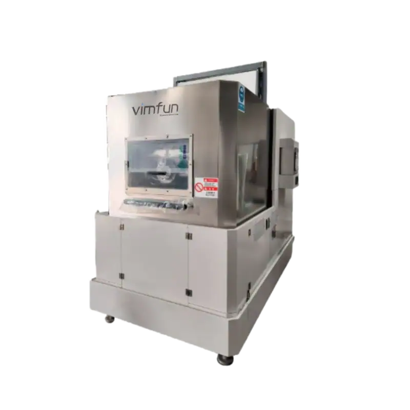
For silicon-ingot squaring and hard, brittle workpieces within a narrower cross-section. Confirm the proposed slice range against your drawing before selecting a wire-web pitch.
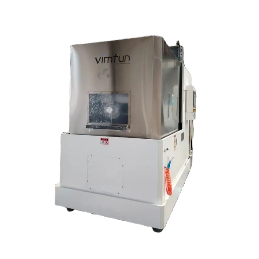
Consider this model for long, repeat-production workpieces. Check width and height as well as length: a longer machine does not automatically accept the larger cross-section handled by SOM400.
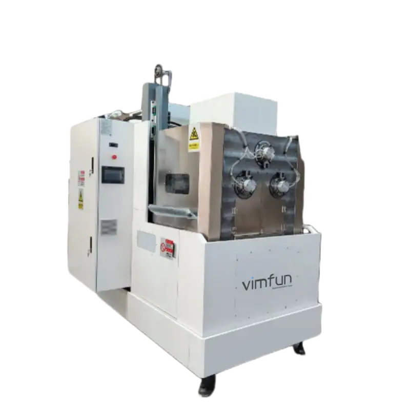
For repeat production of thin, hard-material slices. Compare the required thickness range with SOMIS-400, and evaluate surface condition, fixture support and complete cycle time on the actual material.
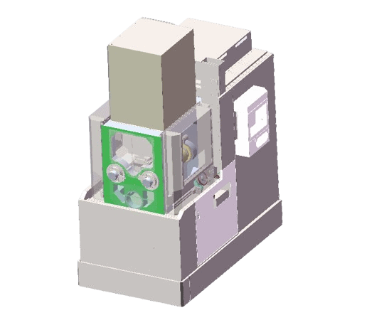
An inverted-cutting option for shorter workpieces and thin slices. Review the mounting arrangement and required finishing allowance together; the listed slice range is not a finished-wafer tolerance.
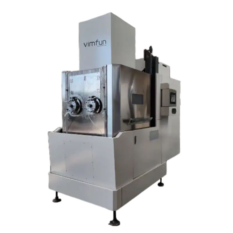
For longer workpieces than SOMI-430 within the same listed width and height. The specified maximum reciprocating wire speed is 2,200 m/min; the working speed must be selected for the material and trial result.
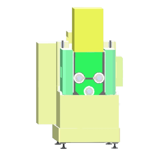
The planned route for silicon carbide and alumina, with sapphire also within the application scope. Compare this wider thickness range with SOMS3-430 when both a swing mechanism and thin slices are under consideration.
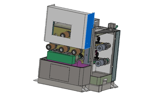
For smaller magnet blocks and straight-slice production. Define the as-cut thickness separately from the final ground thickness, and include holding space and edge support in the loading review.
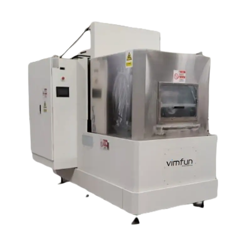
For longer magnet workpieces and a mix of straight slices and arc segments. Send the inner radius, outer radius and thickness of curved parts so the cutting and subsequent grinding route can be assessed.
Dimensions marked × 2 refer to two workstations. Listed slice ranges are not finished-part tolerances. Product images show equipment configurations; confirm the ordered arrangement.
Explore the material guides to narrow the cutting route, machine configuration and sample requirements.
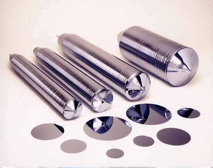
Thin slices, finishing stock and thickness inspection.
Explore application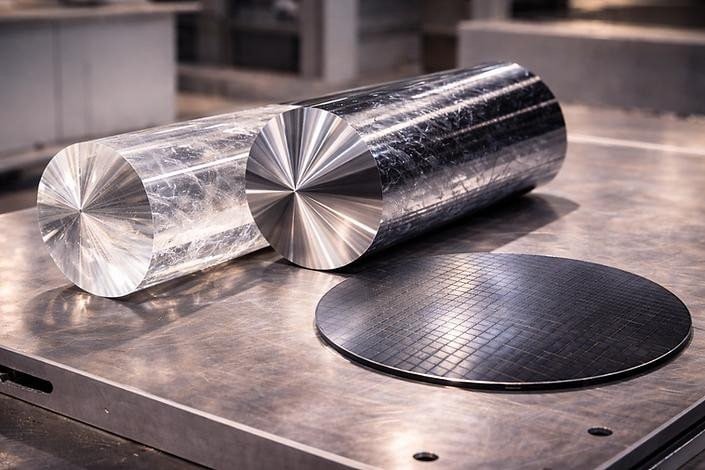
Review the cutting route and surface condition on a trial.
Explore application
Define crystal orientation, cut geometry and edge criteria.
Explore application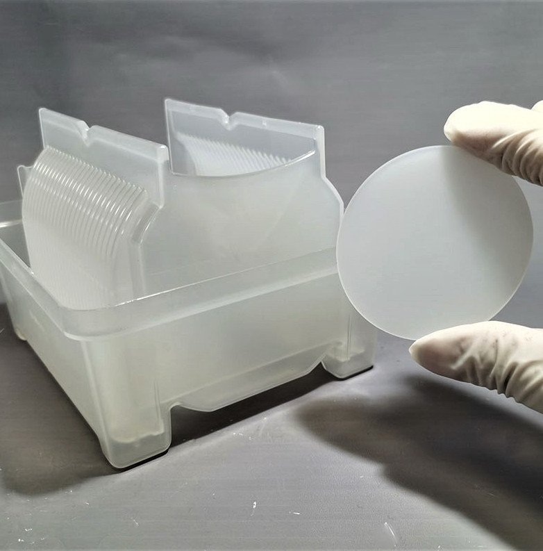
Review wafer support, slice thickness and finishing allowance.
Explore application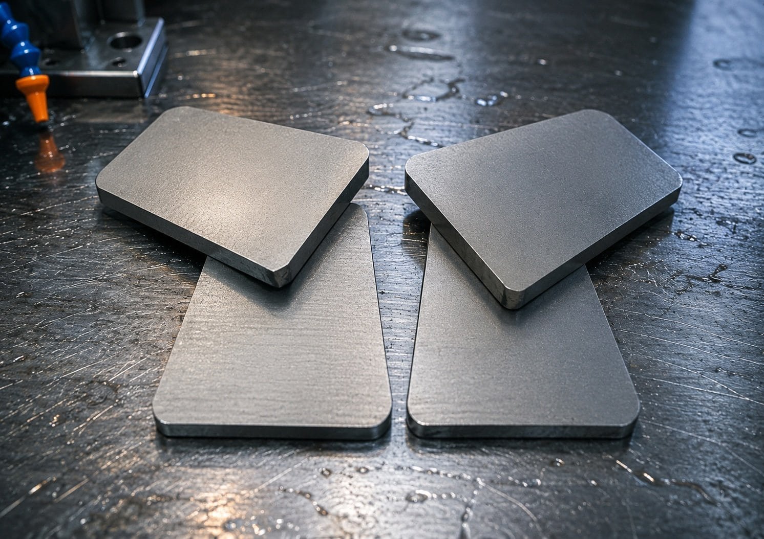
Define magnetized state, slice geometry and grinding allowance.
Explore applicationNeed individual sections rather than parallel batches? Compare wire sawing and sectioning methods.