Kerf and material use
A parallel wire web makes multiple cuts in one feed. Actual kerf depends on the wire and cutting conditions; wire diameter alone is not the measured material loss.

From blank to a qualified slicing process. Match your material, part geometry and inspection requirements to the right SOM configuration.
Discuss your partCompare models10 modelos SOM · 6 grupos de aplicación · Corte de muestra gratuito
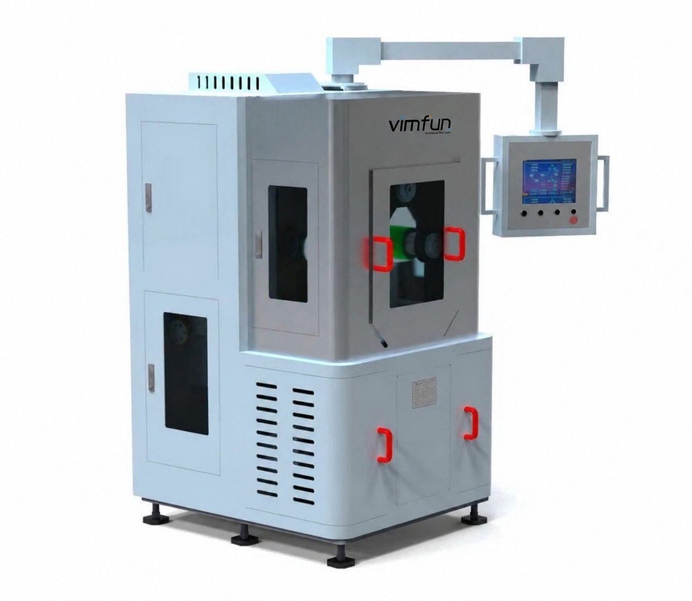
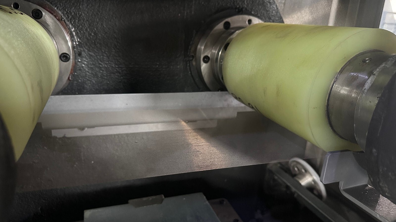
A parallel wire web makes multiple cuts in one feed. Actual kerf depends on the wire and cutting conditions; wire diameter alone is not the measured material loss.
Wire pitch and actual kerf determine the as-cut slice thickness. Allow separately for grinding or polishing before specifying the finished dimension.
Review support, fixture clearance and release of the slices. Assess edge chipping and surface condition on your material before fixing the production settings.
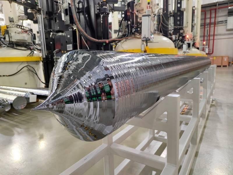
Crop and prepare the ingot to suit the machine envelope before loading.
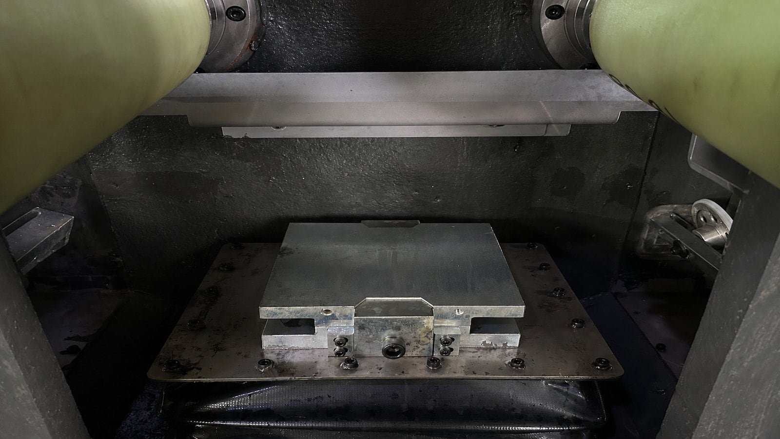
SOM200 fixture before loading. Review support and clearance for the prepared blank.
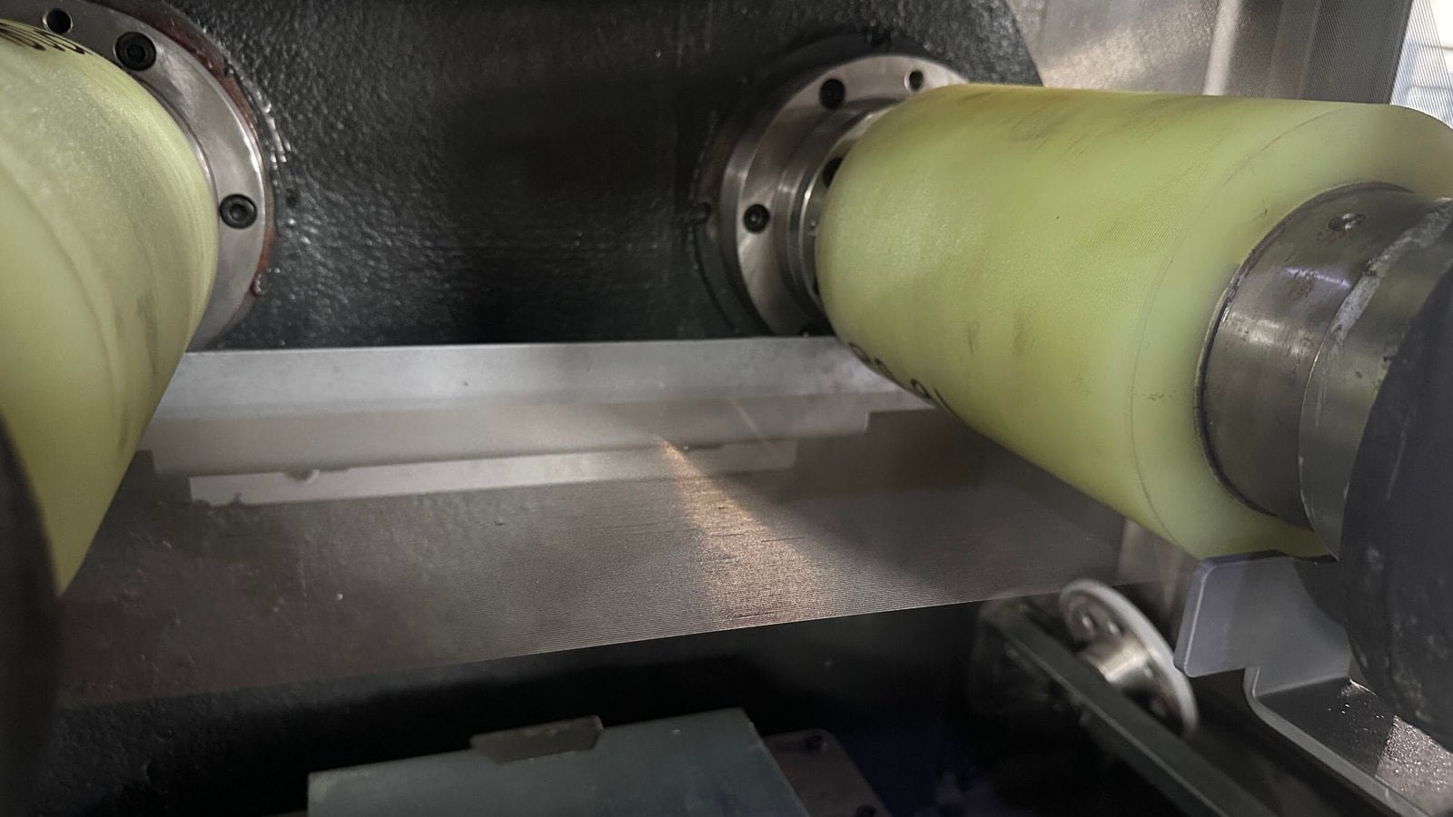
Parallel wire web and guide rollers. Set the cutting conditions for the material and slice requirement.
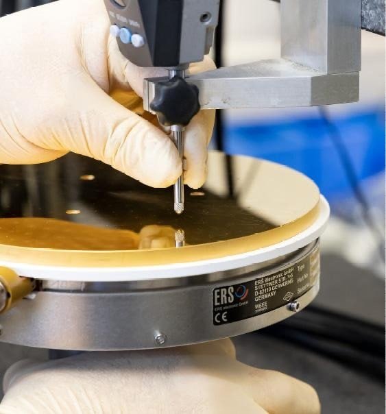
Contact-probe inspection. Agree the measurement method and acceptance criteria for your part.
Images illustrate the individual stages; they do not document a single workpiece or one continuous production run.
Start with the workpiece and cutting route. Then compare the listed envelope and slice range with your fixture and finishing requirements.
Una opción compacta para pequeños lotes, cambios frecuentes de material y desarrollo de procesos. Comience aquí cuando una máquina de producción completa exceda los requisitos de la pieza de trabajo y del lote.
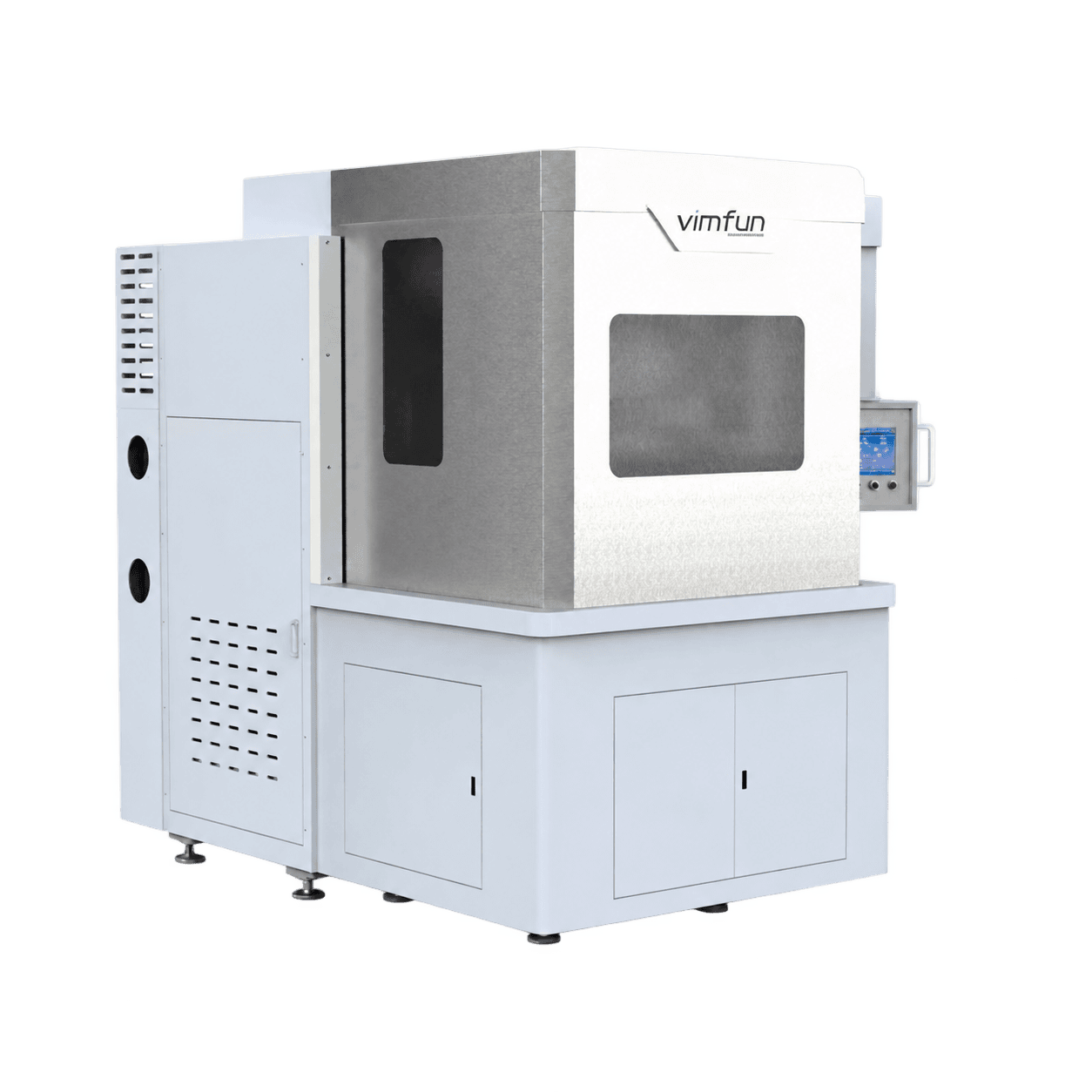
Priorice este modelo cuando la sección transversal de la pieza de trabajo sea la limitación. Su disposición de doble placa de trabajo difiere de simplemente extender la longitud de una palanquilla estrecha. Revise la disposición de dos placas con su fijación.
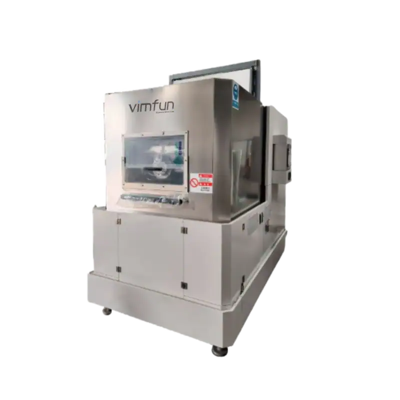
Para el escuadrado de lingotes de silicio y piezas de trabajo duras y quebradizas dentro de una sección transversal más estrecha. Confirme el rango de corte propuesto con su dibujo antes de seleccionar un paso de malla de alambre.
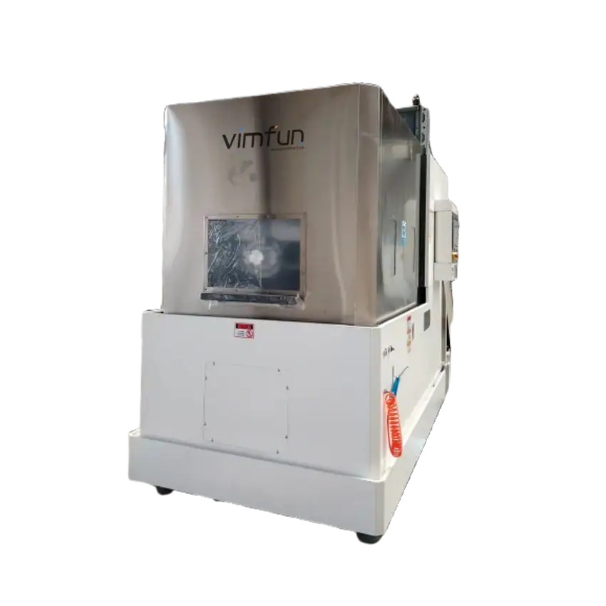
Considere este modelo para piezas de trabajo largas de producción repetida. Verifique el ancho y la altura, así como la longitud: una máquina más larga no acepta automáticamente la sección transversal más grande manejada por SOM400.
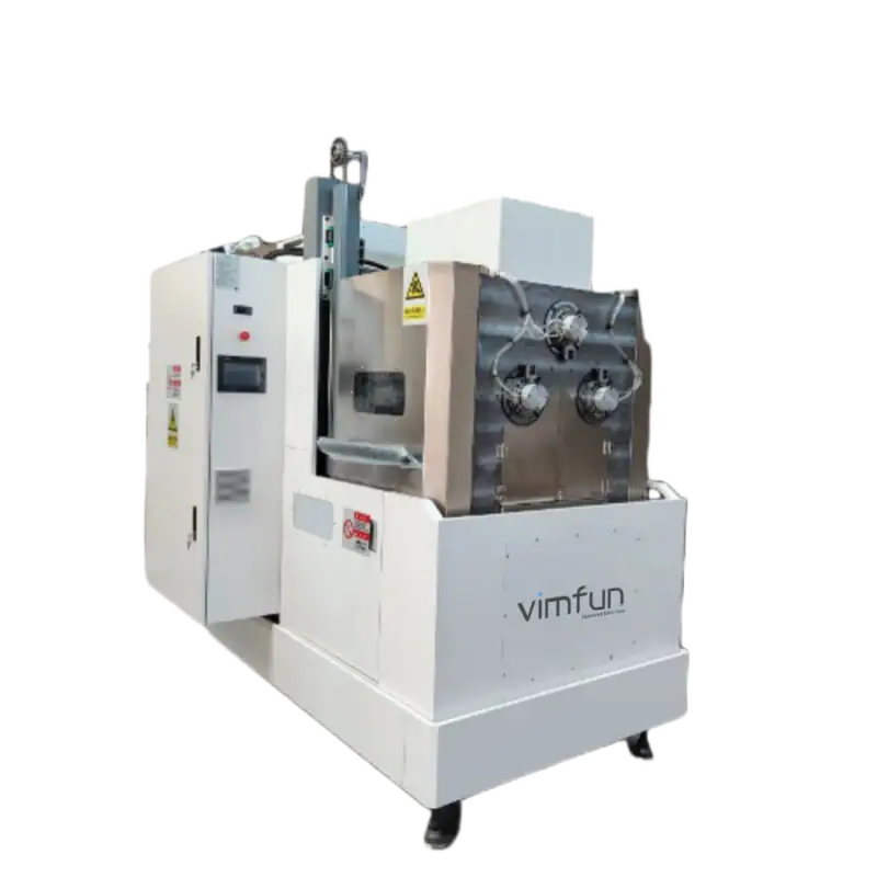
Para la producción repetida de cortes delgados de material duro. Compare el rango de espesor requerido con SOMIS-400 y evalúe la condición de la superficie, el soporte de la fijación y el tiempo de ciclo completo en el material real.
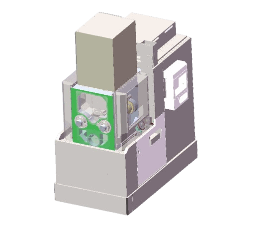
Una opción de corte invertido para piezas de trabajo más cortas y cortes delgados. Revise la disposición de montaje y la tolerancia de acabado requerida juntas; el rango de corte indicado no es una tolerancia de oblea terminada.
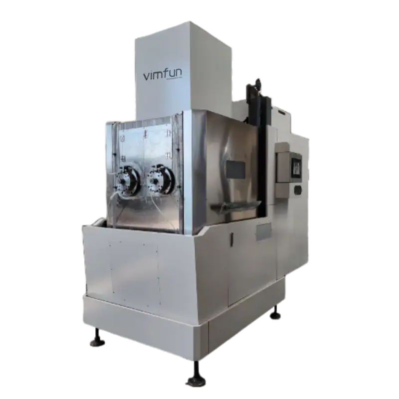
Para piezas de trabajo más largas que SOMI-430 dentro del mismo ancho y alto indicados. La velocidad máxima especificada del alambre de vaivén es de 2200 m/min; la velocidad de trabajo debe seleccionarse para el material y el resultado de la prueba.
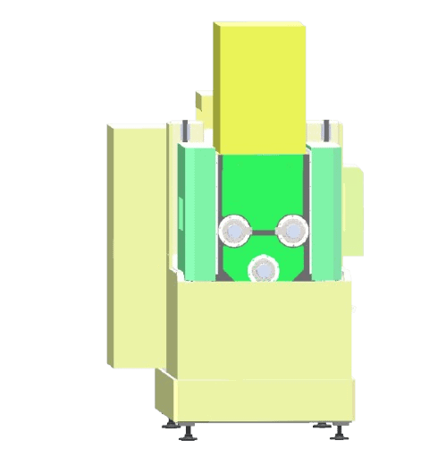
La ruta planificada para carburo de silicio y alúmina, con zafiro también dentro del alcance de la aplicación. Compare este rango de espesor más amplio con SOMS3-430 cuando se consideran tanto un mecanismo oscilante como cortes delgados.
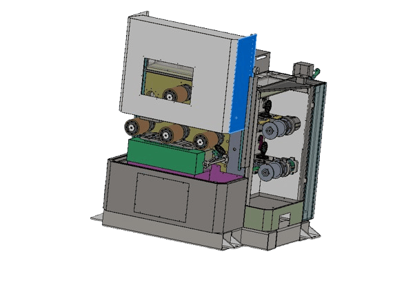
Para bloques de imán más pequeños y producción de cortes rectos. Defina el espesor de corte tal como está por separado del espesor de rectificado final, e incluya espacio de sujeción y soporte de borde en la revisión de carga.
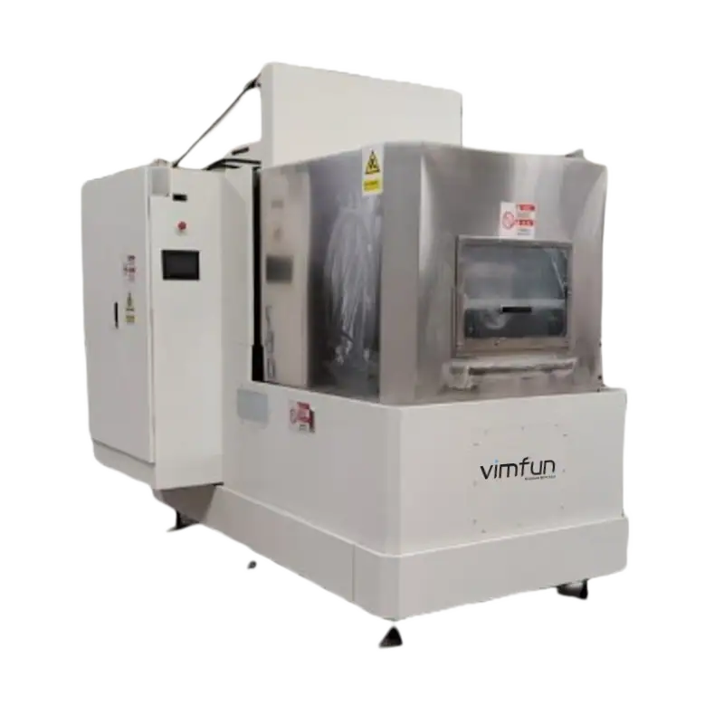
Para piezas de trabajo de imán más largas y una mezcla de cortes rectos y segmentos de arco. Envíe el radio interior, el radio exterior y el espesor de las piezas curvas para que se puedan evaluar la ruta de corte y rectificado posterior.
Dimensions marked × 2 refer to two workstations. Listed slice ranges are not finished-part tolerances. Product images show equipment configurations; confirm the ordered arrangement.
Explore the material guides to narrow the cutting route, machine configuration and sample requirements.
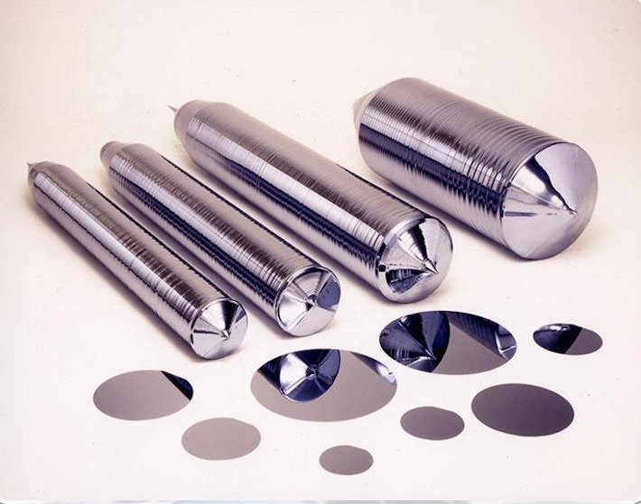
Thin slices, finishing stock and thickness inspection.
Explore application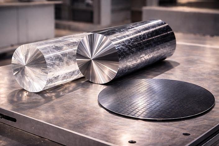
Review the cutting route and surface condition on a trial.
Explore application
Define crystal orientation, cut geometry and edge criteria.
Explore application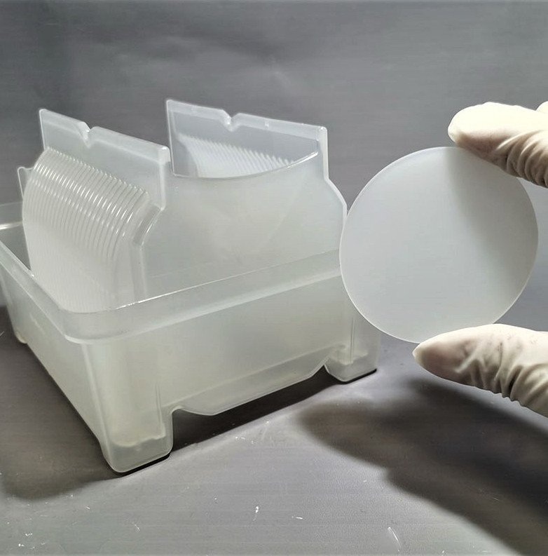
Review wafer support, slice thickness and finishing allowance.
Explore application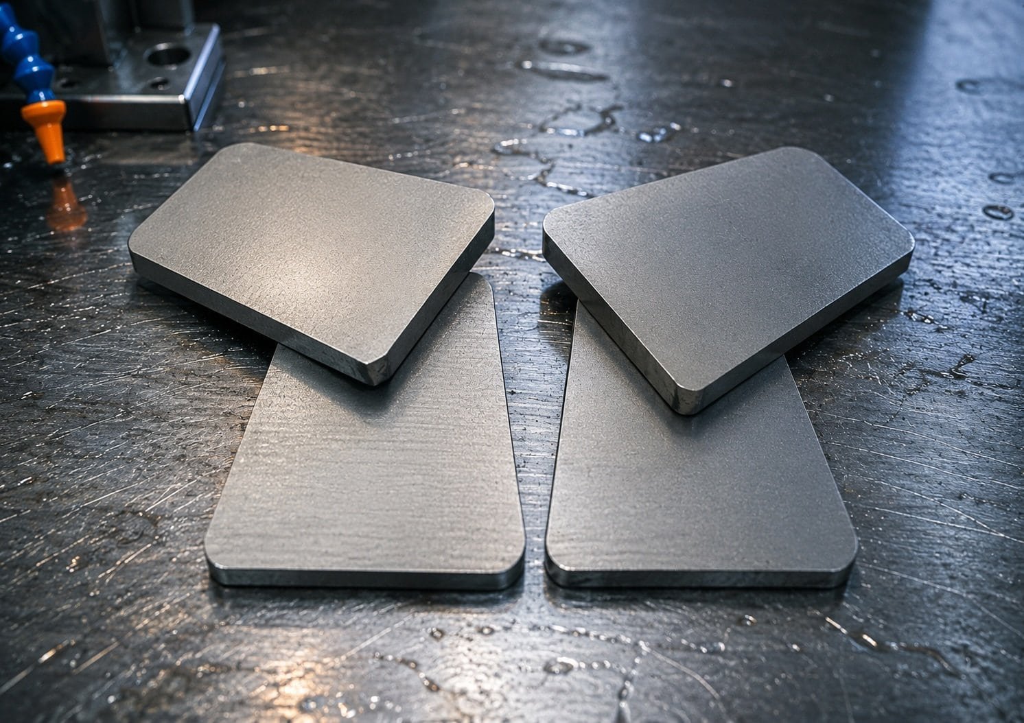
Define magnetized state, slice geometry and grinding allowance.
Explore applicationNeed individual sections rather than parallel batches? Compare wire sawing and sectioning methods.