Kerf and material use
A parallel wire web makes multiple cuts in one feed. Actual kerf depends on the wire and cutting conditions; wire diameter alone is not the measured material loss.

From blank to a qualified slicing process. Match your material, part geometry and inspection requirements to the right SOM configuration.
Discuss your partCompare models10 SOM-Modelle · 6 Anwendungsgruppen · Kostenlose Musterbearbeitung
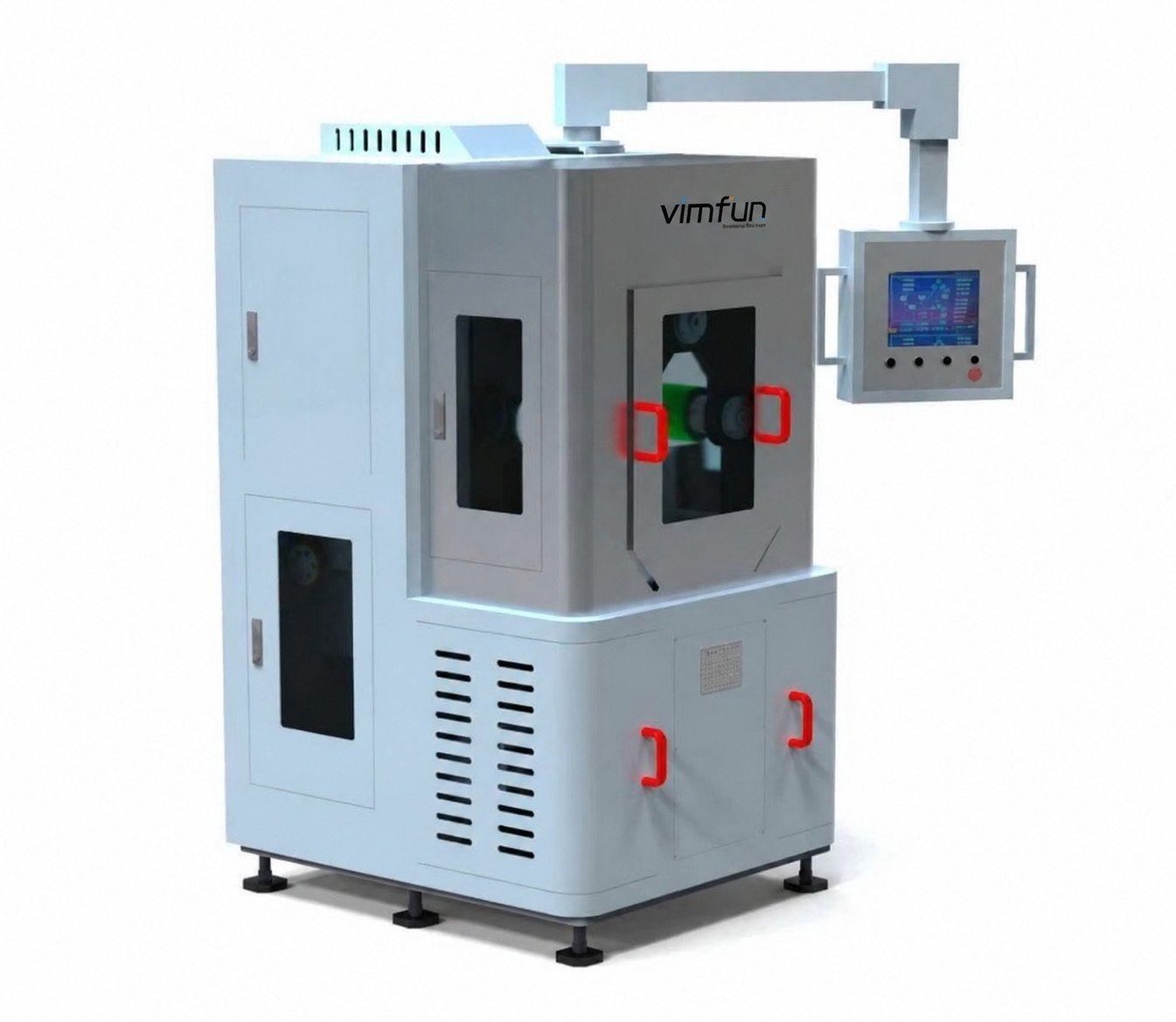
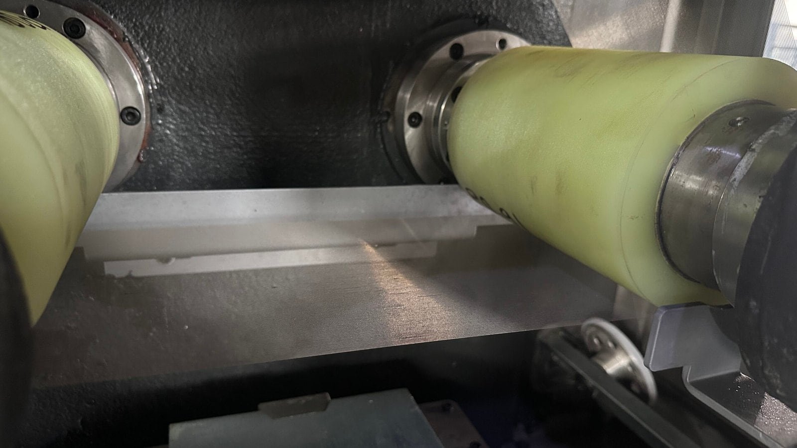
A parallel wire web makes multiple cuts in one feed. Actual kerf depends on the wire and cutting conditions; wire diameter alone is not the measured material loss.
Wire pitch and actual kerf determine the as-cut slice thickness. Allow separately for grinding or polishing before specifying the finished dimension.
Review support, fixture clearance and release of the slices. Assess edge chipping and surface condition on your material before fixing the production settings.
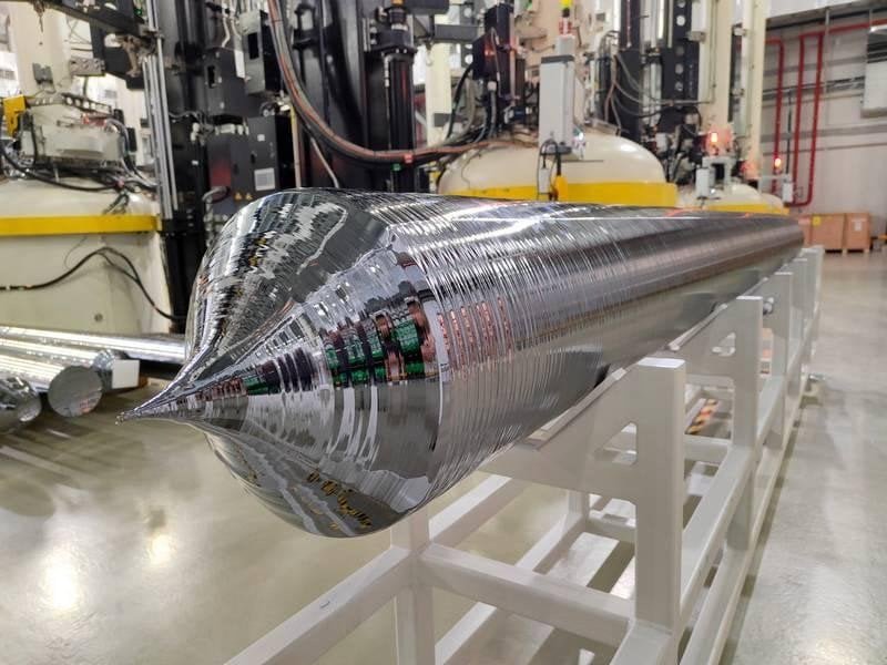
Crop and prepare the ingot to suit the machine envelope before loading.
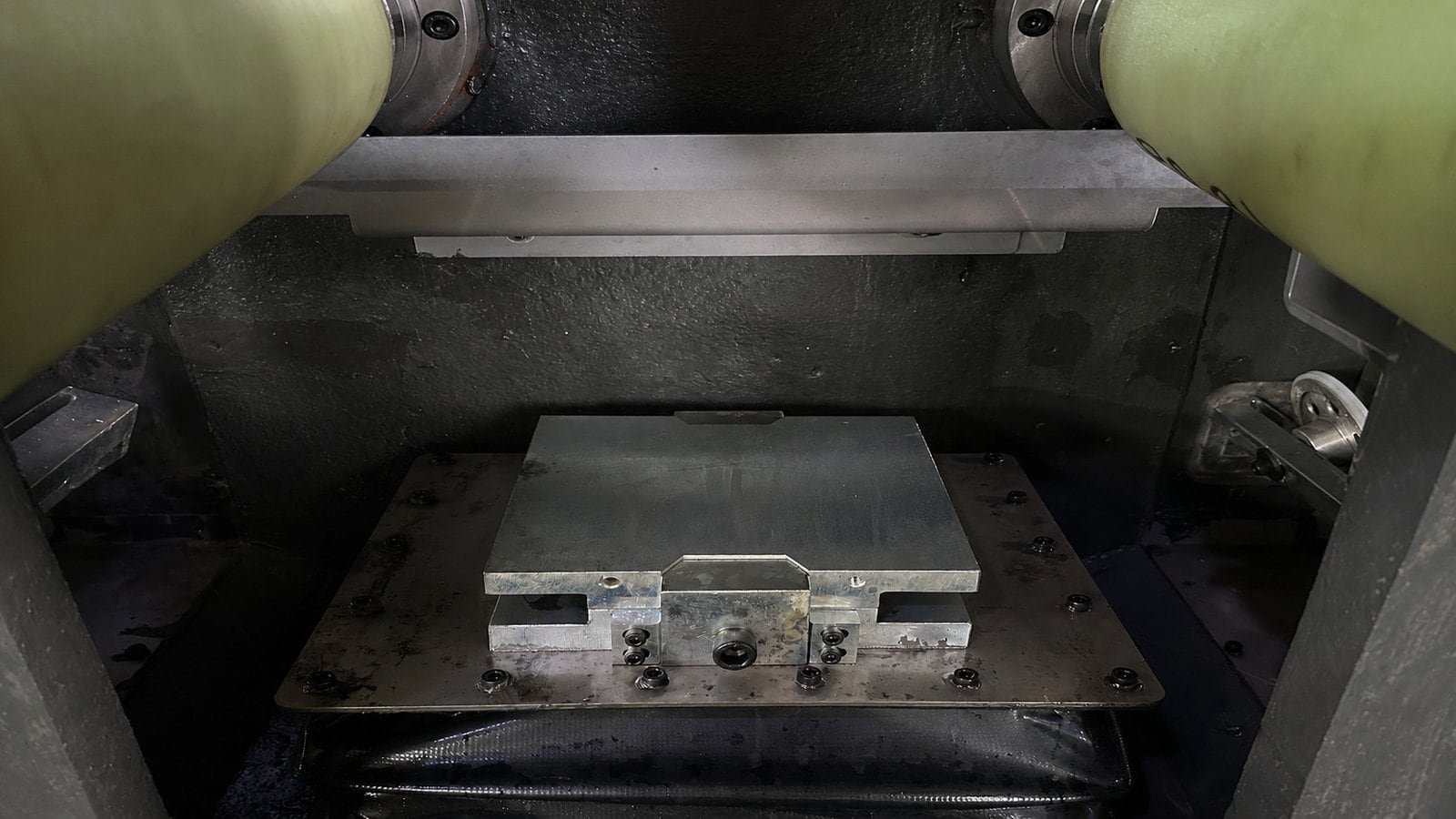
SOM200 fixture before loading. Review support and clearance for the prepared blank.
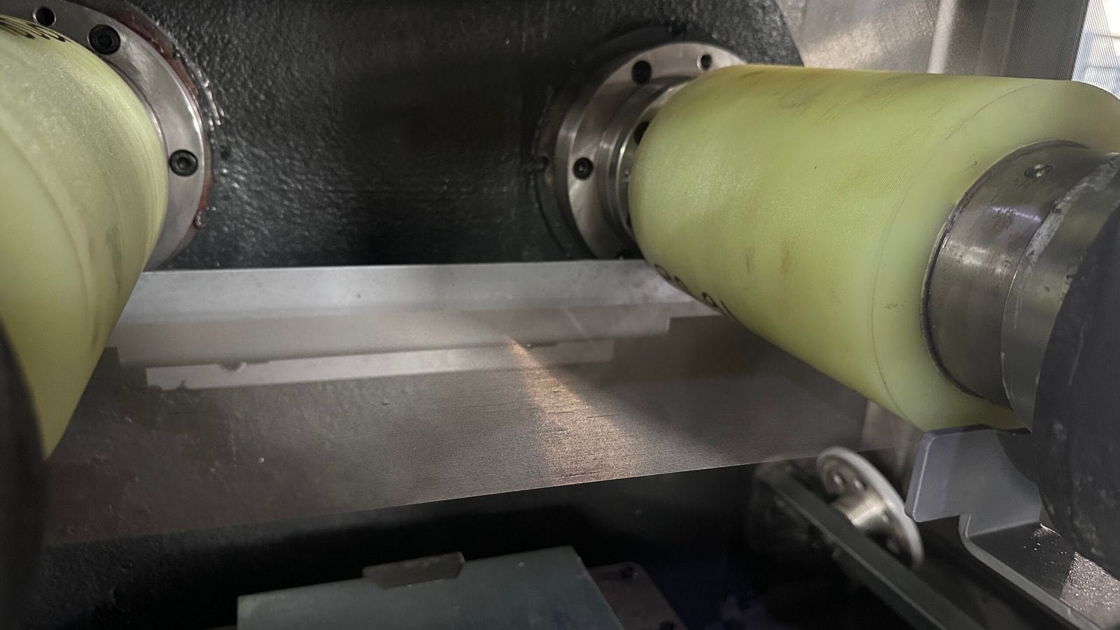
Parallel wire web and guide rollers. Set the cutting conditions for the material and slice requirement.
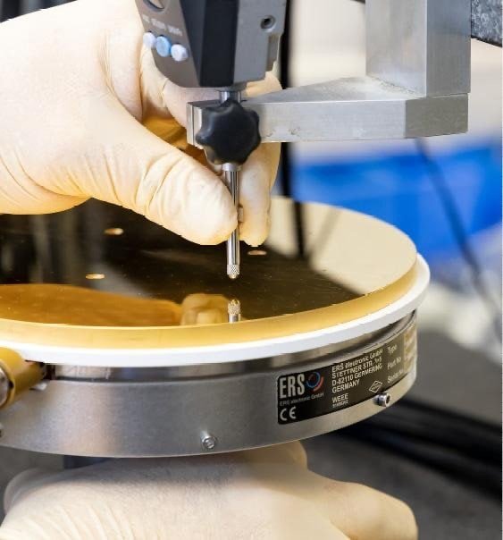
Contact-probe inspection. Agree the measurement method and acceptance criteria for your part.
Images illustrate the individual stages; they do not document a single workpiece or one continuous production run.
Start with the workpiece and cutting route. Then compare the listed envelope and slice range with your fixture and finishing requirements.
Eine kompakte Option für Kleinserien, häufige Materialwechsel und Prozessentwicklung. Beginnen Sie hier, wenn eine volle Produktionsmaschine die Anforderungen an Werkstück und Charge übersteigen würde.
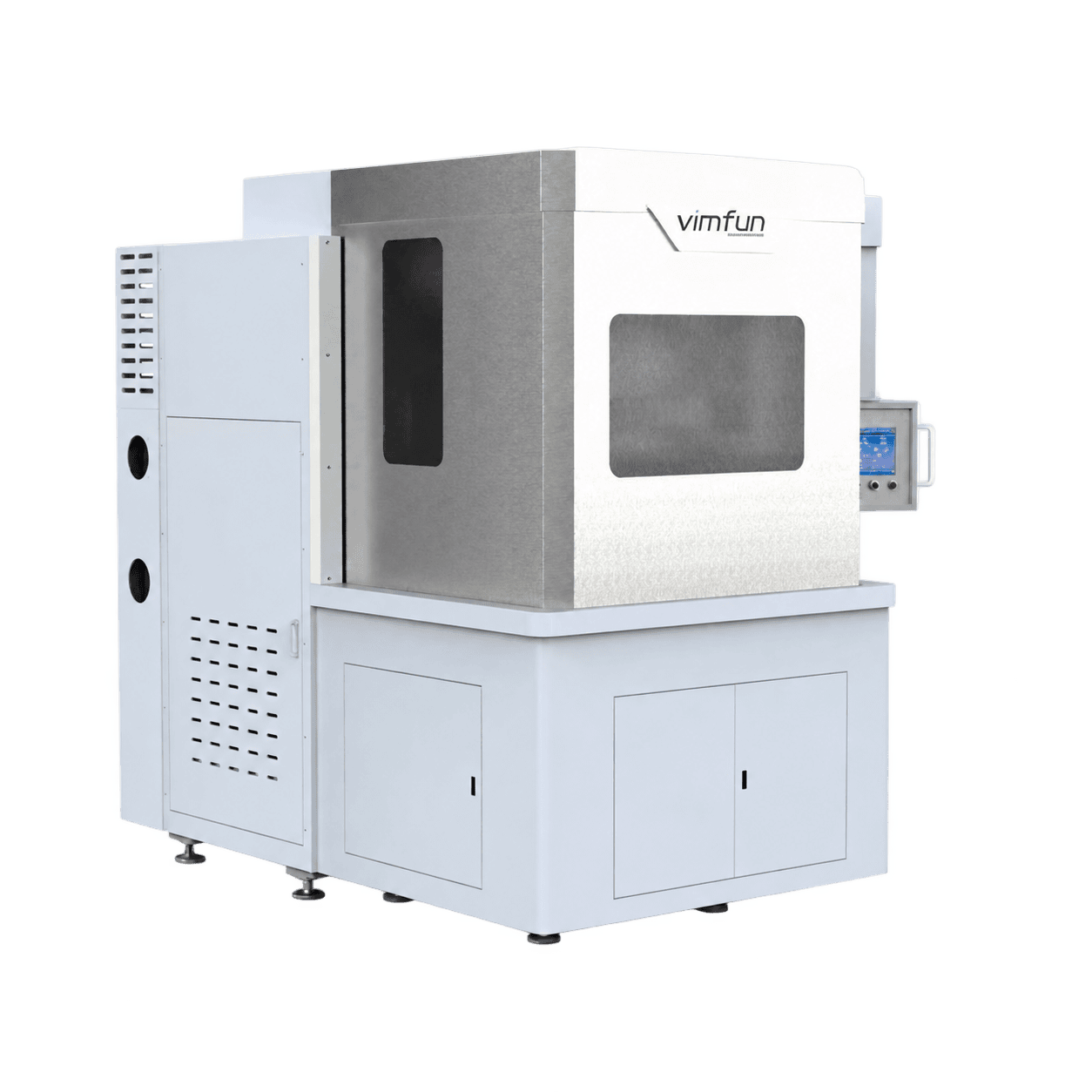
Priorisieren Sie dieses Modell, wenn der Werkstückquerschnitt die Einschränkung darstellt. Seine Doppelplattenanordnung unterscheidet sich vom einfachen Verlängern eines schmalen Rohlings. Überprüfen Sie das Zweiplattenlayout mit Ihrer Vorrichtung.
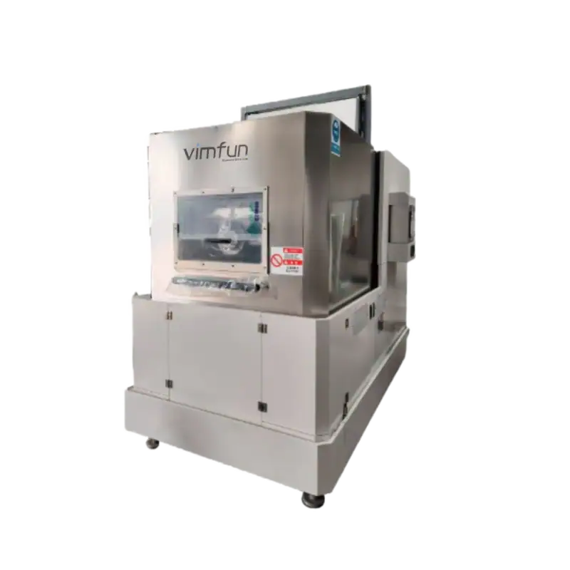
Zum Quaderförmigmachen von Siliziumstäben und harten, spröden Werkstücken mit einem schmaleren Querschnitt. Bestätigen Sie den vorgeschlagenen Schnittbereich anhand Ihrer Zeichnung, bevor Sie eine Drahtnetzsteigung wählen.
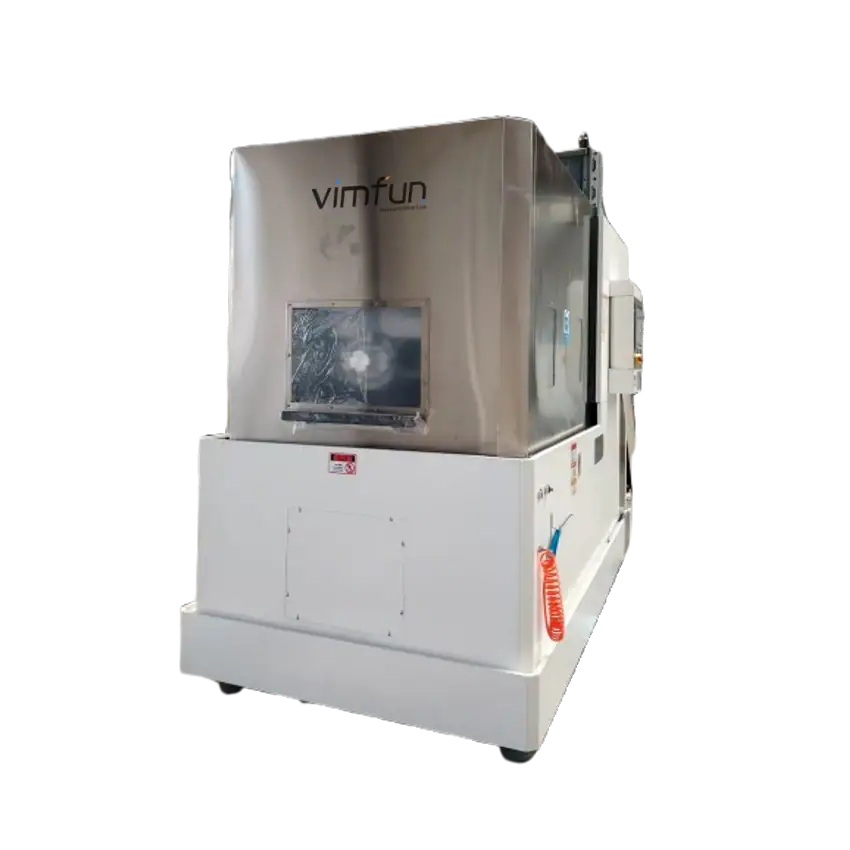
Erwägen Sie dieses Modell für lange Werkstücke in der Wiederholproduktion. Prüfen Sie Breite und Höhe sowie Länge: Eine längere Maschine nimmt nicht automatisch den größeren Querschnitt auf, den SOM400 verarbeitet.
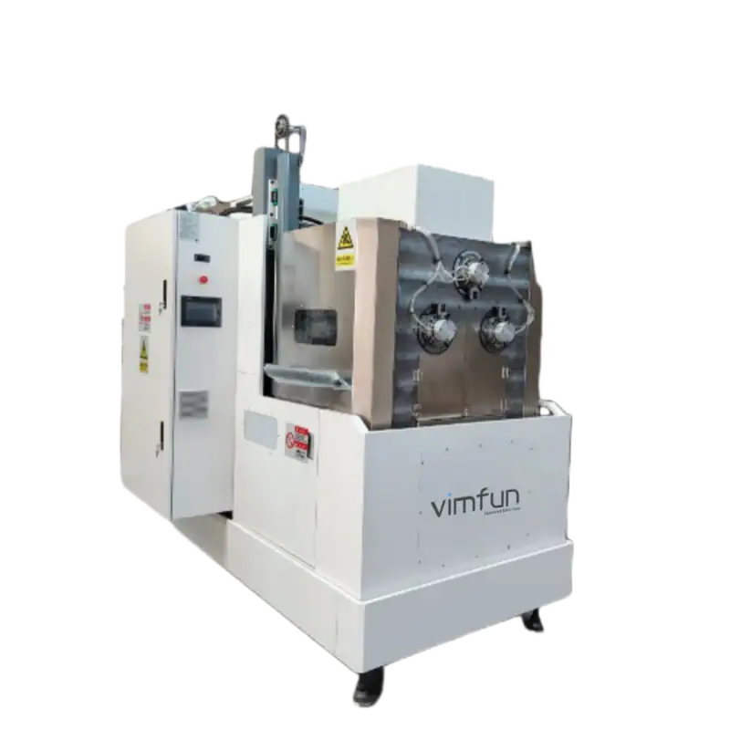
Für die Wiederholproduktion von dünnen, harten Materialschnitten. Vergleichen Sie den erforderlichen Dickenbereich mit SOMIS-400 und bewerten Sie Oberflächenbeschaffenheit, Vorrichtungsunterstützung und die vollständige Zykluszeit am tatsächlichen Material.
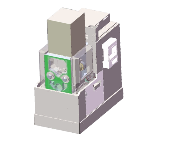
Eine Invert-Schneideoption für kürzere Werkstücke und dünne Schnitte. Überprüfen Sie die Montageanordnung und die erforderliche Nachbearbeitungszugabe gemeinsam; der angegebene Schnittbereich ist keine fertige Wafer-Toleranz.
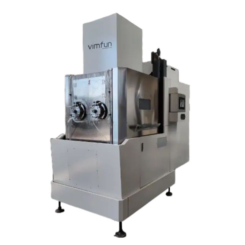
Für längere Werkstücke als SOMI-430 bei gleicher angegebener Breite und Höhe. Die angegebene maximale Hin-und-Her-Drahtgeschwindigkeit beträgt 2.200 m/min; die Arbeitsgeschwindigkeit muss für das Material und das Probeschnittergebnis ausgewählt werden.
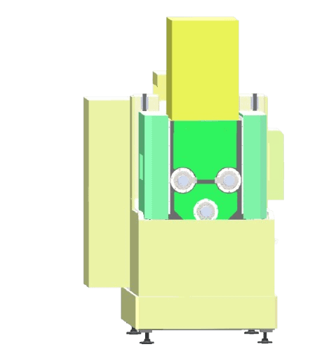
Der geplante Weg für Siliziumkarbid und Aluminiumoxid, wobei auch Saphir im Anwendungsbereich liegt. Vergleichen Sie diesen größeren Dickenbereich mit SOMS3-430, wenn sowohl ein Schwenkmechanismus als auch dünne Schnitte in Betracht gezogen werden.
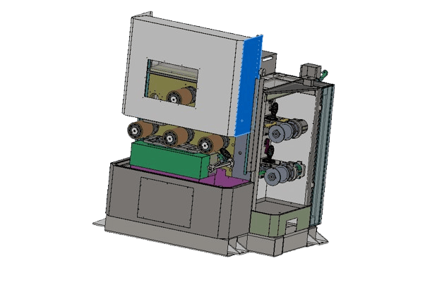
Für kleinere Magnetblöcke und die Produktion gerader Schnitte. Definieren Sie die Dicke nach dem Schnitt separat von der endgültigen Schleifdicke und berücksichtigen Sie den Platz für die Aufnahme und die Kantenunterstützung bei der Überprüfung der Beladung.
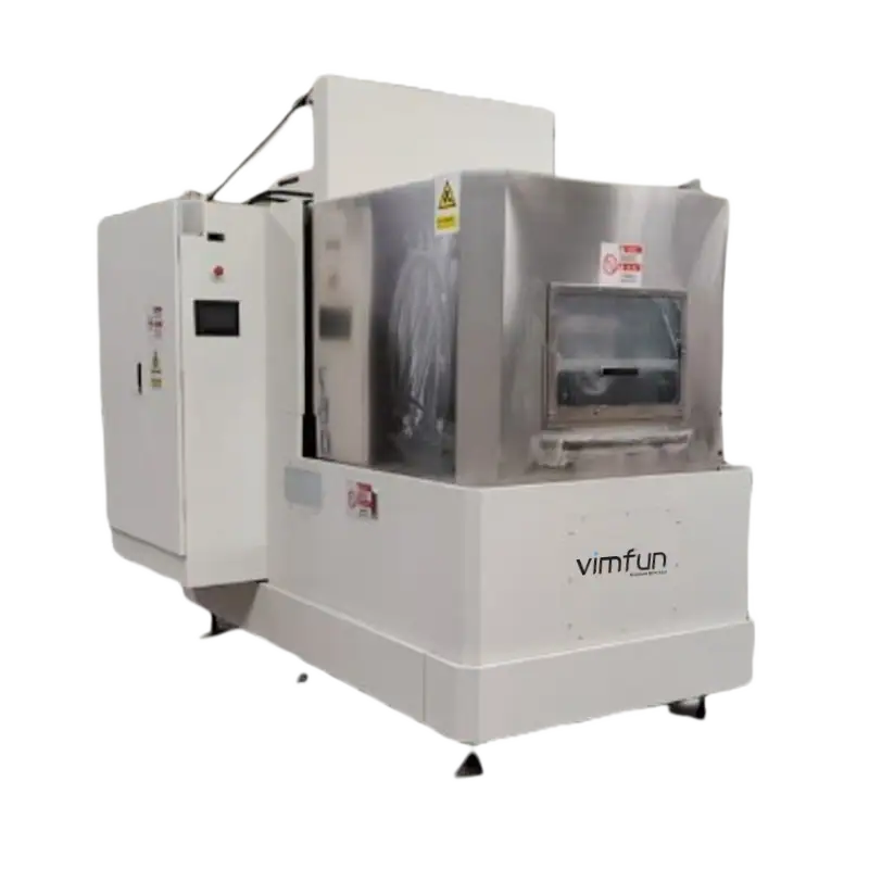
Für längere Magnetwerkstücke und eine Mischung aus geraden Schnitten und Bogensegmenten. Senden Sie den Innenradius, den Außenradius und die Dicke der gekrümmten Teile, damit der Schnitt- und anschließende Schleifweg beurteilt werden kann.
Dimensions marked × 2 refer to two workstations. Listed slice ranges are not finished-part tolerances. Product images show equipment configurations; confirm the ordered arrangement.
Explore the material guides to narrow the cutting route, machine configuration and sample requirements.
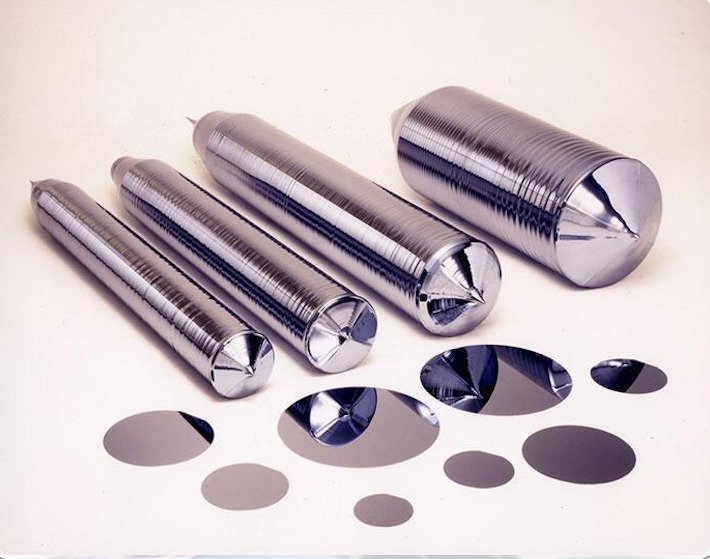
Thin slices, finishing stock and thickness inspection.
Explore application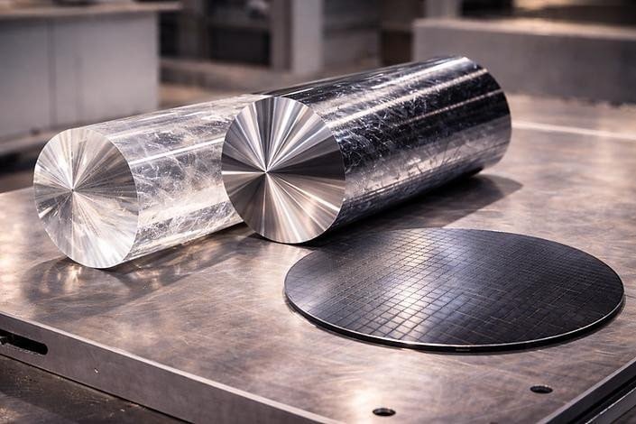
Review the cutting route and surface condition on a trial.
Explore application
Define crystal orientation, cut geometry and edge criteria.
Explore application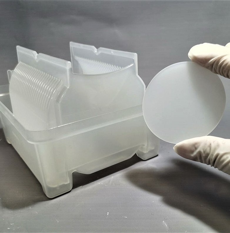
Review wafer support, slice thickness and finishing allowance.
Explore application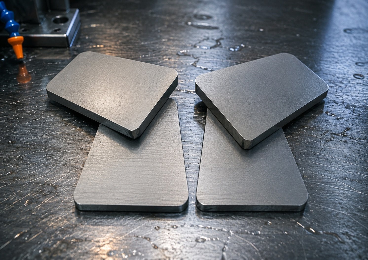
Define magnetized state, slice geometry and grinding allowance.
Explore applicationNeed individual sections rather than parallel batches? Compare wire sawing and sectioning methods.