
Vimfun SOM400 · Single station / Dual work plates
Dual Plate Multi Wire Saw SOM400
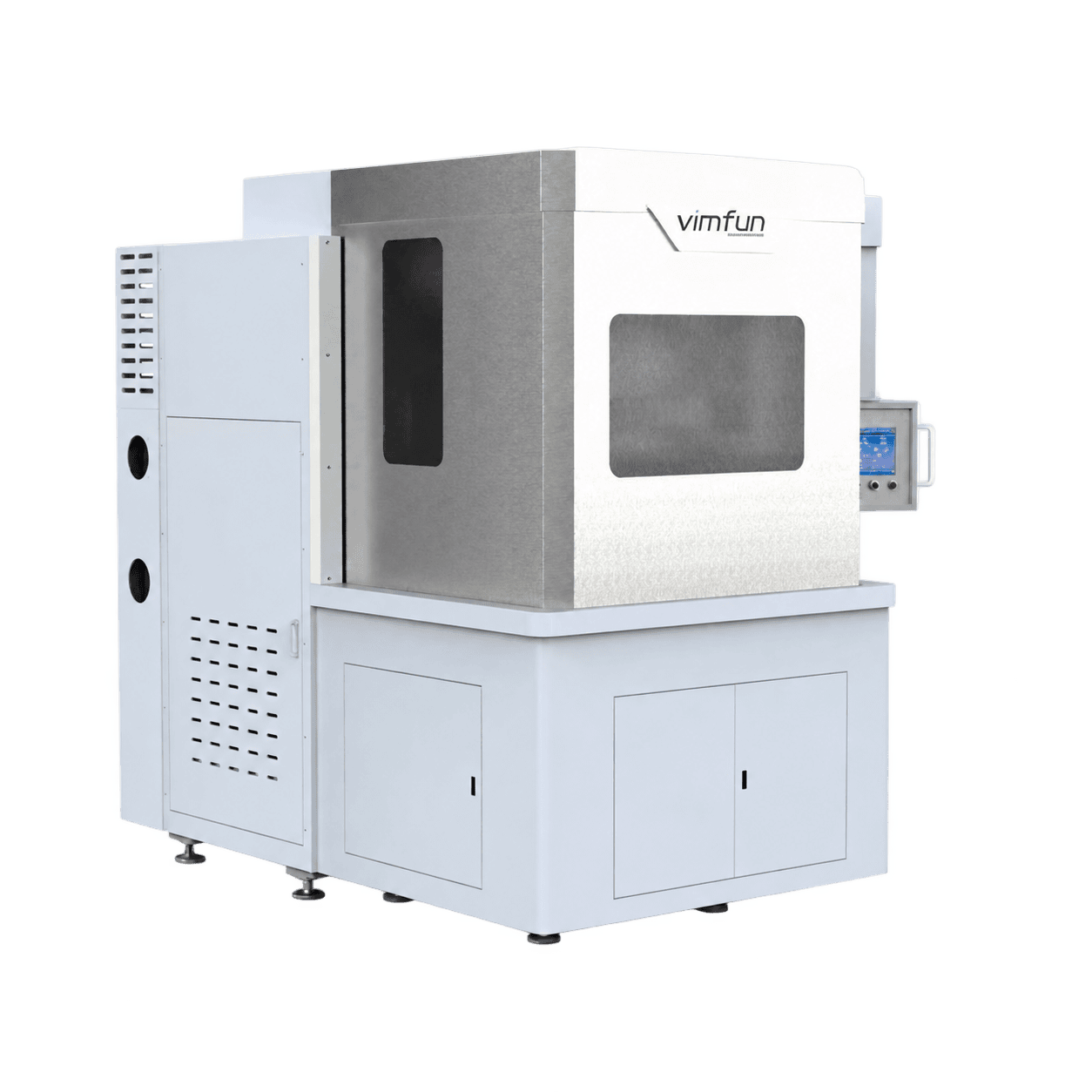
A dual plate multi wire saw for large-section hard and brittle blocks. SOM400 combines two work plates in one station, a listed charge capacity of 400 × 400 × 830 mm and a 1–35 mm slice range.
The charge dimensions describe the loading arrangement, not a separate 400 × 400 × 830 mm allowance for each plate.
Where does SOM400 fit in a block-to-slice process?
Start with an ingot section, sintered block or other prepared workpiece that fits the proposed loading arrangement. The saw creates parallel slices; it does not replace the grinding, lapping or polishing that establishes the finished surfaces. Plan the as-cut thickness together with the allowance required by the next operation.
A large cross-section is the main reason to shortlist this machine. Compare both width and height before choosing by model number: a machine built for a longer, narrower ingot may not accommodate the same section. Fixtures, bonding layers and the unloading method also occupy working space.
For downstream planning, review double-sided lapping and grinding and lapping equipment against your finished-part requirements.
What does a dual plate multi wire saw change?
Two work plates are arranged side by side within one station. Both workpieces are presented to the same cutting process, so the loading plan must account for the material, geometry and cutting requirements of the complete charge. This is a dual work-plate arrangement, not two independently specified production machines.
Use the charge capacity carefully
The specification lists a maximum cross-section of 400 × 400 mm and a charge size of 400 × 400 × 830 mm. Send a drawing of the proposed blocks and fixtures so the usable loading arrangement can be confirmed.
Count accepted output
Two plates can put two workpieces through a cycle. They do not guarantee twice the accepted output of another process. Include bonding, loading, cutting, unloading, inspection and changeover when estimating parts per shift.
How do four rollers establish the cutting web?
Diamond wire travels from the pay-off spool around four grooved rollers to form parallel cutting spans, then onto the take-up spool. The work table feeds the bonded workpieces through the running web. Roller grooves establish cut spacing, while the material removed by the actual kerf determines how much of that spacing remains as slice thickness.
Independent servo drives
Each roller axis has its own servo drive. The specified belt-free arrangement removes belts from the drive transmission. Wire setup, roller condition and maintenance still affect the result.
Reciprocating diamond wire
The specification lists wire speed up to 1,200 m/min and up to eight direction reversals per minute. These are equipment limits; the working recipe depends on material and part requirements.
Controlled wire tension
The listed tension range is 0–32 N. Tension, feed, mounting and wire condition must be considered together. A maximum catalogue setting is not a default production setting.
Measure kerf on the actual cut rather than treating wire diameter as the kerf. For small allowances, agree where and how slice thickness and variation will be inspected before the trial.
Which materials should be considered for this machine?
The source specification lists semiconductor crystals, optical and infrared materials, advanced ceramics and magnetic materials. The list is a starting point for review; it does not mean that one wire and one cutting recipe apply to every material or grade.
| Material family | Examples in the specification | What to define |
|---|---|---|
| Semiconductor crystals | Silicon, germanium, gallium arsenide, indium phosphide | Crystal orientation, incoming section and finishing allowance |
| Advanced ceramics | Silicon carbide, sapphire, alumina, zirconia | Grade, edge condition and sample-cut acceptance |
| Optical and infrared materials | Optical glass, quartz, fused silica, ZnSe, ZnS, CaF₂ | Material identification and the required cut surface |
| Magnetic materials | NdFeB, SmCo, ferrite | Material condition, mounting and downstream process |
The listed slice range is 1–35 mm. It is not a finished-part tolerance and does not establish suitability for every material at the lower limit. For dedicated straight and arc magnet production, compare the options in our magnet machining guide.
Technical specifications
| Cutting capacity | |
|---|---|
| Work stations | 1, with two work plates |
| Maximum charge / loading arrangement | 400 × 400 × 830 mm |
| Maximum workpiece cross-section | 400 × 400 mm |
| Slice thickness | 1–35 mm |
| Listed thickness tolerance | ±0.02 mm |
| Wire speed | 0–1,200 m/min |
| Direction reversals | Up to 8 per minute |
| Wire tension | 0–32 N |
| Take-up spool capacity | 3 km |
| Machine and drives | |
|---|---|
| Grooved rollers | 4, polyurethane-coated |
| Roller diameter | 180 ± 10 mm |
| Roller center distance | 610 mm |
| Spindle runout | ≤0.01 mm |
| Drives | Independent servo drives; no belts |
| Full-load power | 60 kW |
| Main-body dimensions | 1,516 × 2,885 × 2,440 mm |
| Machine weight | Approx. 8 t |
| Wire diameter, feed and table stroke | Confirmed in the technical agreement |
The tolerance is a specification value, not a guarantee for every material and fixture. Validate the required as-cut result through sample cutting. Confirm the final wire configuration, feed settings and delivered dimensions in the technical agreement.
Main assemblies and their role in the process
- One-piece cast frame and wall plate. Provide a rigid support structure for the rollers and cutting area. Frame stiffness is one part of maintaining geometry under the changing loads of reciprocating cutting.
- Spindles and grooved rollers. Carry the cutting web and establish the wire positions. The specification lists spindle runout of ≤0.01 mm; roller condition and groove selection remain setup considerations.
- Wire pay-off and take-up. Manage the wire supply and collection. The fixed-spool traverse arrangement lays the wire without shuttling the entire reels back and forth.
- Work table and dual plates. Carry the bonded workpieces through the web. Review fixture clearances, charge balance and access for unloading the sliced material.
- Motorized enclosure. Provides access for loading when raised and encloses the cutting area during operation. Site layout and safe operating requirements are confirmed for the delivered configuration.
- Cooling and process control. Support control of the cutting conditions. Coolant compatibility and the operating recipe must be reviewed for the supplied material.
SOM400, SOM4-630D or SOM4-1000D?
These machines serve production work, but their capacities describe different shapes and loading arrangements. SOM400 emphasizes cross-section; the other two emphasize longer, narrower workpieces. Compare all dimensions and the part drawing before choosing an industrial multi wire saw.
| Model | Listed workpiece / charge | Main selection reason |
|---|---|---|
| SOM400 | 400 × 400 × 830 mm, dual work plates | Large cross-section and two-plate loading |
| SOM4-630D | 630 × 160 × 150 mm × 2 | Silicon squaring and narrower production blocks |
| SOM4-1000D | 1000 × 200 × 150 mm × 2 | Long workpieces and repeat production |
If your workpieces fit within 200 × 200 × 200 mm and you mainly run laboratory batches, review SOM200 before selecting a larger machine. For inverted, swing-assisted and dedicated thin-slice options, return to the complete SOM model guide.
What should be checked before a production order?
Define the incoming charge
Send the material grade, block dimensions, number of workpieces and proposed holding surfaces. A large format multi wire saw must accommodate the fixture and loading method as well as the nominal block dimensions.
Agree the acceptance criteria
Separate the as-cut dimensions from the finished dimensions after grinding or lapping. Include required thickness variation, edge condition, measured kerf and the allowance available for finishing.
Review the full production cycle
Evaluate cutting time alongside preparation, bonding, loading, unloading, inspection and changeover. Record the number of accepted pieces per batch so productivity comparisons use the same definition of output.
Plan installation with the order
Power supply, coolant, compressed air, foundation, lifting access, service space and site safety requirements are confirmed with your order — please ask us. Main-body dimensions alone are not an installation plan.
Warranty and service
CE certified · 12-month warranty · Response within 12 hours · Free sample cutting.
Share your intended materials and production requirement so the equipment configuration and trial scope can be discussed before the final technical agreement.
Send your block dimensions and target slice thickness
Include the material grade, finished-part drawing, proposed batch arrangement and required accepted output.
Request free sample cutting- Material and grade
- Block and fixture dimensions
- As-cut thickness and finishing allowance
- Batch size and changeover requirements
CE certified · 12-month warranty · 12-hour response · Free sample cutting