Kerf Loss in Wafer Slicing: How Wire Diameter Sets Material Yield
Understand cutting width, blank thickness and the material balance behind accepted wafer yield.
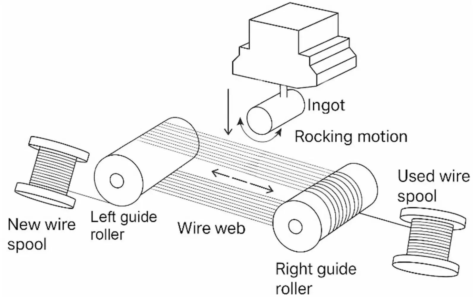
Kerf loss is the material removed between retained slices during cutting. Reducing it can increase the number of blanks available from an ingot, but only if those blanks survive release and finishing. A smaller nominal wire diameter tells you one tool dimension; it does not tell you the actual cut width, the stock left in the blank or how many finished substrates will pass inspection.
Start the comparison with usable ingot length, required blank thickness and measured or justified effective cutting width. Then count accepted output. This keeps a kerf loss calculation from becoming an optimistic slice-count claim.
Vimfun equipment should be compared at the specified blank requirement. The planned thin-wafer product link below provides the equipment context; this article does not assign a measured cutting width to a catalogue model.
How Kerf Loss Enters the Material Balance
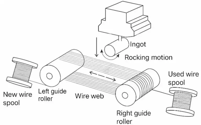
Consider one repeating slice interval: a blank occupies part of that interval and the cut occupies the rest. Over a long usable section, small changes in effective cutting width accumulate. End allowances, incomplete final slices and material rejected after cutting also matter, so a simplified spacing calculation is only a planning estimate.
Research on material removal mechanisms shows why the saw should be treated as a process rather than a static dimensional divider. The IIT Bombay research summary on silicon slicing describes kerf as a material-efficiency consideration in comparing cutting approaches. Its experimental context does not establish a production guarantee for another machine or material.
Is wire diameter the same as cutting width?
For a kerf loss wire saw comparison, distinguish the wire core from its abrasive-coated envelope and the effective cutting width. The first is a tool dimension, the second includes the cutting layer, and the third describes the material removed. A thinner core does not establish the last quantity by itself.
The nominal wire dimension helps define tool selection, but the abrasive system, wire motion and cutting condition influence the width actually removed. Measure or infer the effective cut using an agreed method. Do not write a purchase specification that assumes every micrometre of wire reduction becomes an equal reduction in kerf loss.
Guide condition and tracking also deserve attention. A tool that follows an unstable path may sacrifice the benefit of a smaller nominal dimension. A comparison that changes wire type, mounting and operating conditions simultaneously cannot isolate which change affected the result.
Keep the terminology consistent in quotations and reports. Ask whether a stated dimension refers to the wire core, an overall abrasive-coated diameter, groove spacing or measured cutting width. These numbers describe different things and should not be placed in a single table column labeled simply “kerf.”
What thickness belongs in the yield calculation?
A wafer's specified final thickness does not necessarily equal its as-cut thickness. Later finishing removes material to achieve the required surface and geometry. If the trial leaves inadequate finishing stock, a low kerf loss figure may accompany a high reject rate.
Ask the finishing team to define the acceptable blank window before comparing saw configurations. Record both the target and allowable variation. A thinner blank may be useful for one route but unsuitable for another route that must remove more damaged material.
For equipment configurations intended for thin blanks, consult the ultra thin wafer slicing machine information. A product's thin-slice positioning is a starting point for evaluation; the particular material and downstream acceptance still need a representative trial.
Use a Calculation with Visible Assumptions
For a simplified estimate, let usable length be L, required blank thickness be t and effective cutting width be k. Ignoring end effects, the count is approximately L divided by the repeating interval t plus k, rounded down. State the convention for the final cut because real workholding may change that boundary.
As an illustrative calculation only, imagine 100 mm of usable stock, 1 mm blanks and a 0.2 mm effective cut. The repeating interval is 1.2 mm; reducing the cut to 0.15 mm changes it to 1.15 mm. These invented example values explain arithmetic, not any Vimfun specification or achievable setting.
That estimate concerns geometric recovery. It does not account for broken slices, finishing rejects or portions excluded from the ingot. Report kerf loss as one term in the material balance rather than presenting the estimated slice count as guaranteed output.
Using the illustrative numbers above, floor(100 / 1.20) gives 83 repeating intervals, while floor(100 / 1.15) gives 86. That is a difference of three in this simplified calculation, not a measured increase from a machine. The first and final cut conventions still need checking against the fixture.
The trap is putting finished thickness into the denominator when the saw actually leaves a thicker blank. A kerf loss calculation then overstates the available count before a single cut has been made. Use the approved as-cut target, including finishing stock, and identify the effective width as measured or assumed.
I'd compare two yield columns: separated blanks and accepted blanks after the receiving process. If the narrower configuration produces more pieces but fewer accepted substrates, it has not solved the production problem. Kerf loss remains useful as a diagnostic term, but the purchasing decision follows accepted recovery.
Three extra geometric intervals are not three accepted substrates.
Count Accepted Material, Not Just Separated Pieces
A cut can produce many pieces that fail the receiving operation. Count acceptable blanks using a definition agreed before the test. Include thickness, edge condition and whatever surface requirements affect the subsequent process. Separate material awaiting inspection from confirmed accepted output.
For multi-line batch production, the multi wire saw overview helps frame the equipment comparison. The important yield question is how the repeated cutting intervals translate into usable blanks under the same acceptance criteria.
When comparing kerf loss between runs, preserve the starting geometry. A longer usable section or smaller end allowance can increase output even if the effective cutting width is unchanged. Record those changes instead of crediting all of the improvement to the wire.
When is the narrower cut a poor trade?
A narrower tool choice must still maintain stable cutting and acceptable output. The operating window can depend on material, unsupported span, fixture condition and the abrasive system. There is no universal wire selection that maximizes material recovery for every crystal.
Assess cutting time, interrupted runs, consumable use and finishing demand alongside kerf loss. A configuration that saves a small amount of stock but requires extensive rework may be less useful than the established process. Conversely, valuable material can justify a slower route if accepted recovery improves.
Do not assume that a visible rough surface measures the depth of subsurface damage. Surface appearance and internal defects require different evaluation methods. Ask the downstream team how it verifies that the planned finishing allowance is sufficient.
Design a Comparison That Can Be Interpreted
Begin with a baseline material lot and document the usable input. Hold the fixture, measurement method and acceptance limits constant where practical. Identify which variable is deliberately changed and list any unavoidable differences. Without that record, the test can demonstrate output but cannot explain causation.
Collect the slice positions, accepted count and rejection reasons. Measure thickness using the same sampling pattern across both runs. If possible, return representative accepted and rejected blanks for finishing evaluation rather than sending only the visually best examples.
A kerf loss report should include a material balance with a clear denominator. State whether recovery is expressed by mass, volume, nominal slice count or accepted finished parts. Different denominators can reverse an apparent improvement.
Calculate the Material Fraction Removed
For a repeated interval with blank thickness t and effective cutting width k, the cutting fraction is k / (t + k). This describes the repeated section only; it excludes cropped ends, mounting stock and later finishing removal. State that boundary beside the percentage.
Using the same illustrative values, 0.2 / 1.2 gives about 16.7%, while 0.15 / 1.15 gives about 13.0%. These are arithmetic examples, not measured machine results. The difference is approximately 3.6 percentage points of that repeated interval, not a promised gain in finished yield.
A mass balance answers a different question. Weighing retained material against usable input can include broken pieces or residual attachment material unless those categories are separated. Slice count, retained volume and accepted finished output are useful measures, but they should not share an unlabeled yield column.
Match Wire Selection to the Required Blank
The wire must remove material while maintaining a stable path. Core size, abrasive envelope, supported span and guide condition belong to the cutting configuration. A smaller dimension is worth comparing when the configuration can still deliver the specified blank thickness and damage condition. A reduction in kerf loss that creates extra finishing demand can lose its material advantage downstream.
Use the ultra thin wafer slicing machine page for the relevant equipment configuration. Request the actual tool dimensions and material-specific trial evidence rather than deriving cutting width from the product category.
In a comparison, retain the same usable input, as-cut thickness target and final acceptance criteria. Record which wire configuration changes. Evaluate complete cutting and finishing effort as well as accepted output; a thinner cut is an engineering option, not an automatic production improvement.
Choose the Page That Answers Your Question
This article answers: Does a narrower cutting interval actually increase accepted output? It does not replace the following equipment or application scopes.
| Your question | Relevant page | Boundary |
|---|---|---|
| Which configuration is intended for thin blanks? | ultra thin wafer slicing machine | Equipment configuration and its stated scope |
| How does batch wire slicing equipment differ? | multi wire saw | Application or process context for the receiving task |
| How is material loss evaluated for NdFeB? | NdFeB material-loss discussion | Application or process context for the receiving task |
FAQ
Is wire diameter a direct measurement of kerf loss?
No. Kerf loss concerns material removed by the cut. A nominal tool dimension is an input, not a direct measurement of effective removal. Identify the abrasive-coated dimension and the measurement method before using either value in a yield estimate.
Can lower kerf loss accompany lower accepted yield?
It can accompany poorer accepted recovery if the resulting blanks fail release or finishing requirements. Compare accepted parts under the same receiving criteria. Do not use a larger separated-piece count as proof that the overall route improved.
Which controls make a kerf loss trial comparable?
Keep the material boundary, blank target and acceptance method equivalent, and name the variable deliberately changed. Record unavoidable differences and tool condition. Kerf loss arithmetic then supports the investigation instead of disguising different products as a performance comparison.
Apply the Method without Transferring Material Claims
The accounting approach also helps when evaluating magnets, but the material behaviour and downstream process remain different. The NdFeB material-loss discussion addresses that application. Do not transfer a silicon cutting result into a magnet yield guarantee.
For a new trial, supply the actual stock geometry, required thickness and inspection plan. Ask for a record of effective cutting condition, output and rejected material. The resulting evidence makes kerf loss useful in purchasing decisions instead of leaving it as a headline percentage.
The most credible improvement is a repeatable increase in accepted recovery under unchanged requirements. Kerf loss is worth reducing, but it should be judged together with finishing and quality. That combination protects the value of the ingot as well as the economics of the cut.
Build the baseline from one material lot and one finishing requirement. Record usable length, blank target, cutting width, end allowance, separated count and accepted count. Recalculate kerf loss only after those boundaries are fixed. The next trial should change a named variable, such as the wire configuration, rather than change the fixture, acceptance limits and tool together.