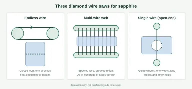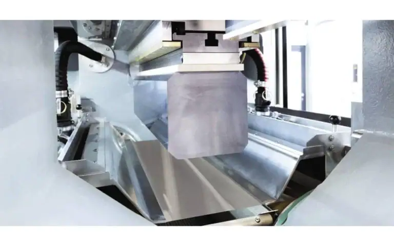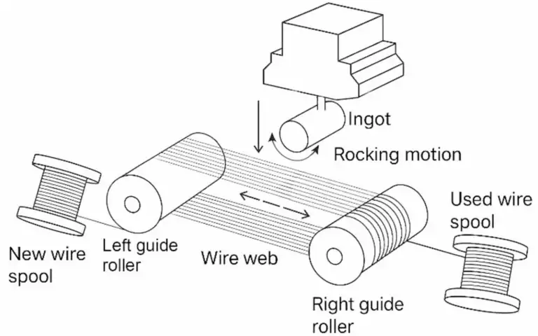
Oscillating multi-wire cutting combines a moving diamond-wire web with a controlled rocking movement of the workpiece. In the SOMIS-400 design, the worktable makes a small-angle reciprocating swing while the wire travels back and forth across the roller system. These are two separate motions: wire reciprocation provides the cutting movement, while workpiece rocking changes how the material meets the wire web.
This guide explains the mechanism and the questions to resolve in a cutting trial. For model specifications and configuration options, see the SOMIS-400 oscillating multi wire saw.
How does oscillating multi-wire cutting work?
The workpiece is secured to the table and fed into the cutting web. On SOMIS-400, three synchronously controlled spindles support the reciprocating wire system. The table adds a small rocking movement during the cut. The product documentation describes this movement as a way to reduce the instantaneous contact area and distribute cutting load more evenly.
That design objective does not establish a finished-slice tolerance or a guaranteed cycle-time saving. Material condition, wire selection, feed settings and workholding still need to be assessed together.
| Motion or feature | What it means on SOMIS-400 | What it does not establish |
|---|---|---|
| Wire reciprocation | The diamond wire travels back and forth through the roller system. | Wire reversal alone does not mean the workpiece is rocking. |
| Worktable swing | The clamped workpiece rocks through a controlled small angle. | No universal swing angle or frequency is specified here. |
| Feed direction | Upward or downward feed is selected for the ordered configuration. | Do not assume automatic switching between both configurations. |
| Three-spindle structure | Describes the model’s roller and spindle arrangement. | Does not mean three independently programmable contour-cutting axes. |
Which materials should be evaluated?
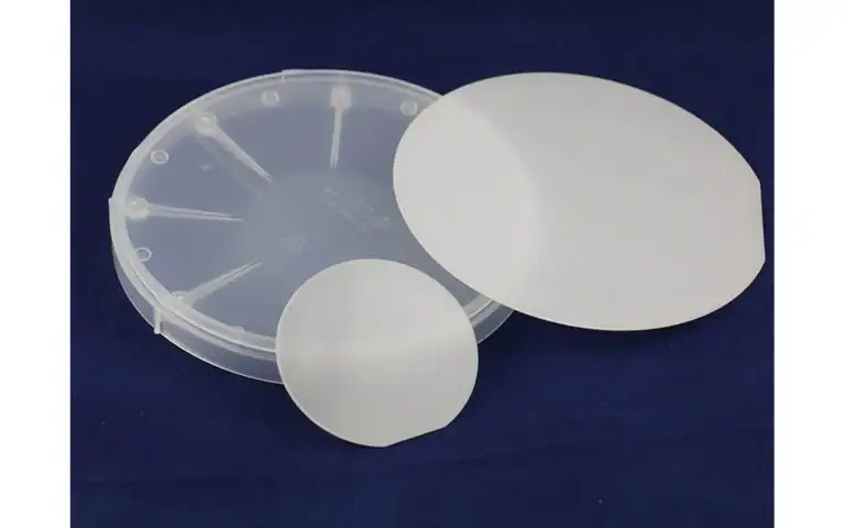
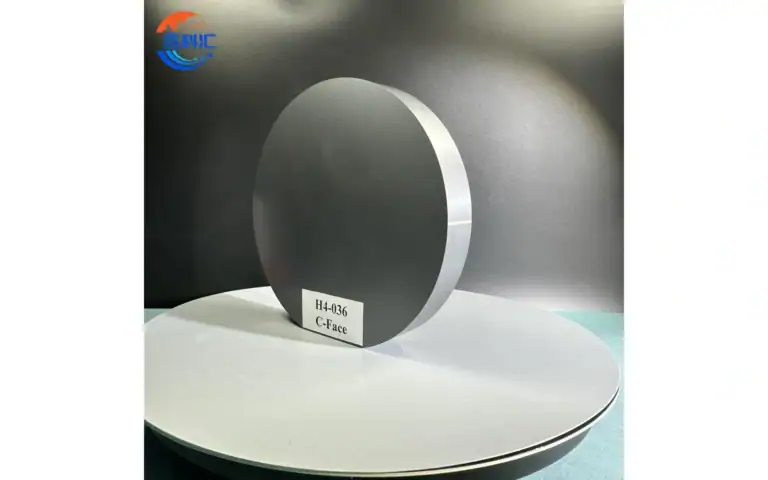
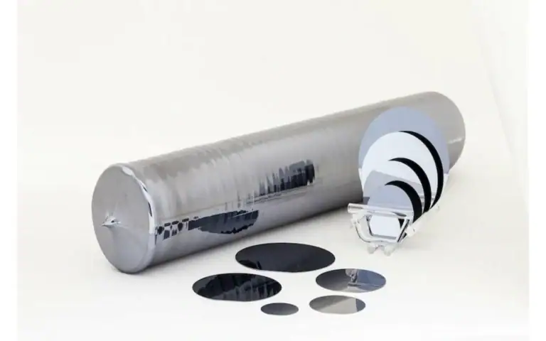
SOMIS-400 is positioned for silicon carbide and alumina, with sapphire also included in the application scope. The relevant task is slicing a hard, brittle blank or preparing suitable blank geometry. Successful slicing is not the same as delivering a finished semiconductor substrate: downstream processing and acceptance requirements must be specified separately.
Provide the material grade, blank dimensions, orientation requirements and known defects before selecting a trial. A result from one material or blank geometry should not be used as a guaranteed result for another. For sapphire-specific application context, see the sapphire slicing page.
What can rocking change, and what still needs testing?
Changing the contact condition is the purpose of the swing mechanism. Whether it produces an acceptable improvement in cutting time, edge condition or wire consumption must be measured on representative material. The available documentation does not provide a controlled comparison with enough trial conditions to support a universal percentage improvement.
Compare results using the same acceptance criteria. Record the blank geometry, wire specification, feed program, coolant conditions and whether swing was enabled. The SOMIS-400 documentation allows the swing function to be stopped when the process requires conventional feed; any comparison should use an agreed operating procedure.
- Slice quality: measure thickness and thickness variation at agreed locations, and inspect edge chipping and surface condition.
- Usable output: count accepted slices after inspection, rather than only pieces produced.
- Time: distinguish cutting time from loading, setup, unloading and inspection.
- Consumables: record wire use and replacement events alongside the cutting conditions.
- Finishing allowance: check whether enough stock remains for the required downstream process.
The precision slicing quality checklist provides further guidance on defining inspection requirements.
What limits the equipment choice?
Rocking capability alone is insufficient for selecting a machine. Check the blank envelope, fixture clearance, required slice range, wire specification and ordered feed direction against the model documentation. Published operating limits should not be treated as a validated recipe for a particular material.
Workholding and the trial method must account for the table’s movement. Confirm the fixture arrangement and operating settings with the equipment team before cutting. No general swing-angle or swing-frequency recommendation is given here because those settings require application-specific confirmation.
Compare available configurations in the multi-wire machine selection overview, then use the SOMIS-400 product page for this model’s specifications.
What should you send for a sample-cutting review?
Send a drawing or dimensioned blank description, material grade, intended slice thickness, quantity, finishing allowance and inspection criteria. Include the proposed clamping surfaces and any orientation requirements. Ask the team to define which conditions will be recorded and what constitutes an acceptable sample before the trial starts.
Discuss a representative sample-cutting trial for your material and required output.