Sapphire Crystal Orientation: C-, A-, R- and M-Plane Wafers
Specify the crystallographic plane and reference direction before the blank is prepared for slicing.
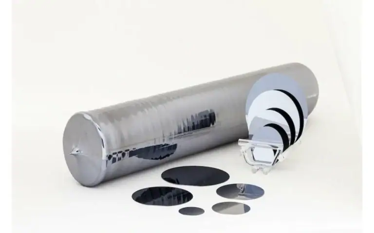
Sapphire orientation can be wrong even when diameter and thickness pass. Confirm the named plane and directional reference before cropping removes the supplier's mark. If a miscut is required, an angle without its axis and sign convention is an incomplete instruction.
For C-, A-, R- and M-plane work, keep the crystal requirement separate from the mechanical datum used by the fixture. Sapphire orientation is established by the specified reference and measurement; it cannot be reconstructed from the outside shape of an unmarked blank.
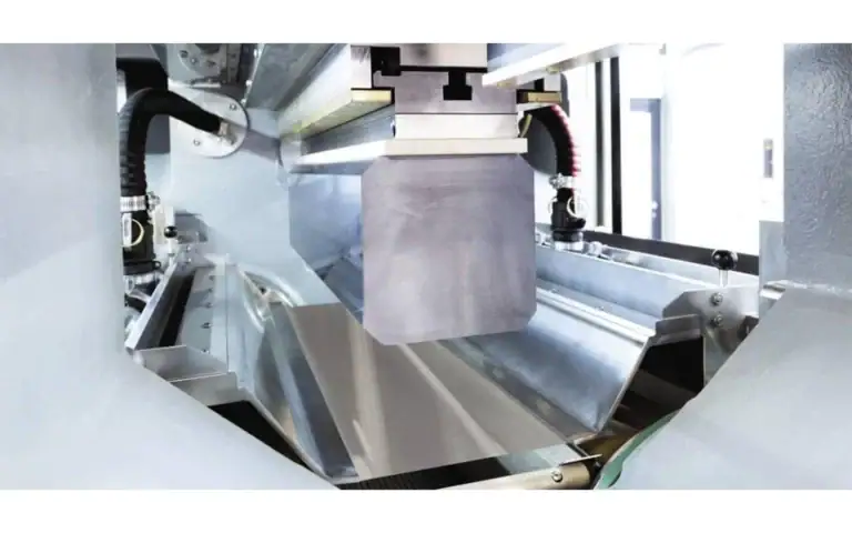
Vimfun SOMIS-400 identifies sapphire slicing among its applications. For sapphire orientation work, that is a machine reference rather than an orientation guarantee; the supplied crystal record and the mounting reference must establish the required plane.
Understanding Sapphire Orientation and Plane Names
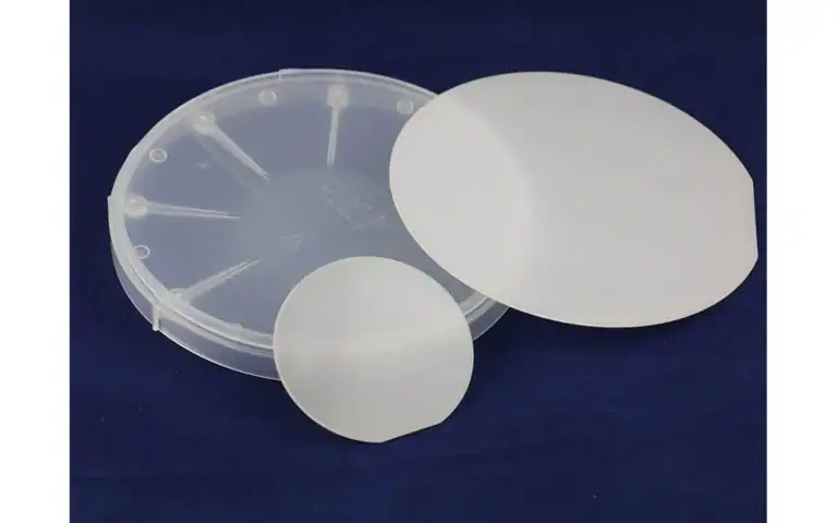
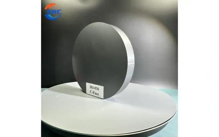
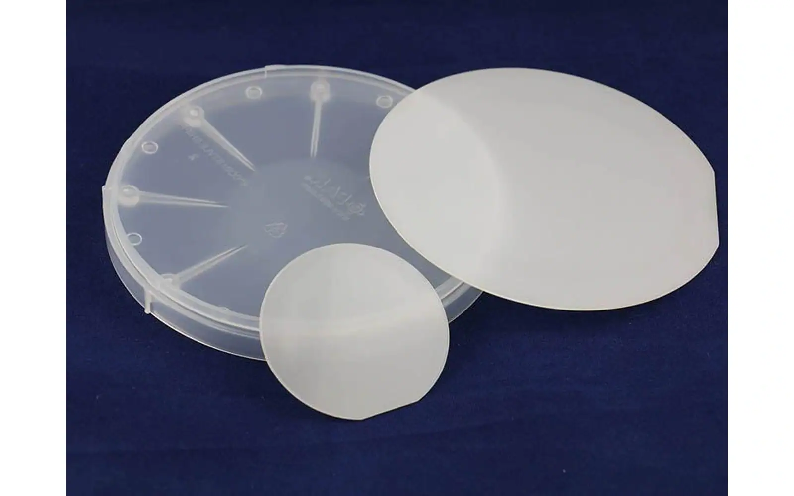
C plane sapphire refers to a wafer whose intended surface follows the basal (0001) plane, subject to the specified orientation tolerance or miscut. It does not mean any sapphire plate with a convenient flat face. C-, A-, R- and M-plane wafers share a material composition but present different lattice planes to the receiving process.
Sapphire is crystalline aluminium oxide. C, A, R and M are conventional names for different crystallographic planes, rather than different chemical compositions. In the commonly used four-index notation, C is (0001), A is (11-20), R is (1-102) and M is (10-10). The negative indices must be represented correctly in controlled drawings.
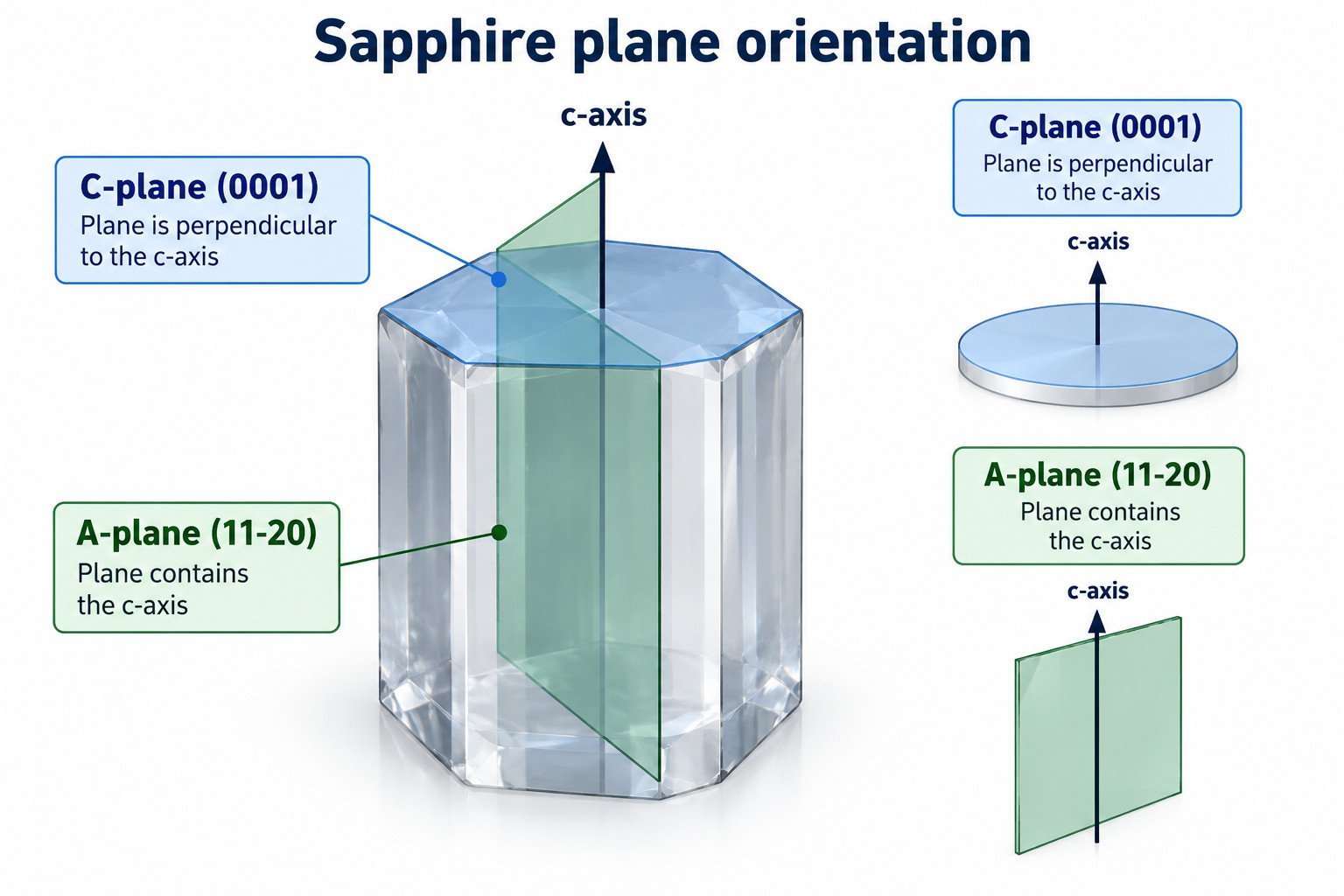
The sapphire reference provides material background. For procurement, use the supplier's crystallographic certificate and the customer's drawing rather than an informal diagram as the authority. A naming convention does not define the allowed deviation from the plane.
What is missing from a plane name?
An orientation label identifies the plane, but a complete wafer requirement can also include its directional reference, an intentional offset and the tolerance associated with those features. Those requirements should come from the receiving process, not be chosen by the saw operator.
When ordering sapphire orientation, state whether the wafer is intended to lie on a nominal plane or a specified miscut. Describe the reference axis and sign convention if an offset is involved. Without them, two suppliers can interpret the same short description differently.
Keep the outside shape separate from the crystal description. A circular wafer, rectangular plate or cropped block can each require the same plane. Diameter and thickness measurements do not verify crystal orientation.
Preserve the Incoming Reference
The material supplier should identify the crystal and its orientation by the approved documentation or marking method. Before cutting, establish how those references relate to the fixture. Do not remove a mark during cropping and then reconstruct its position from memory.
Sapphire orientation records should accompany the workpiece through mounting and release. Include the lot number, reference description and any authorized transfer of the mark. If the fixture obscures the reference, provide another documented way to check alignment before the cut.
A photograph helps record where a mark was located, but it cannot replace orientation measurement. If orientation is a critical acceptance feature, identify the verification method and the organization responsible for it before the trial starts.
Write the conventional planes as C (0001), A (11-20), R (1-102) and M (10-10), using proper overbar notation in the controlled drawing where possible. Plain-text minus signs can become ambiguous when copied into labels. Keep the supplier's original certificate rather than relying on a rewritten caption.
For sapphire orientation, I would ask the receiving team to approve the reference-transfer sketch before the first cut. Show which mark or measured feature establishes the plane and how that feature relates to the fixture. The pitfall is losing a crystallographic reference during an otherwise routine external shaping operation.
A thickness map and an orientation check belong in separate report fields. One describes the blank's geometry; the other describes its relationship to the lattice. Sapphire orientation remains unverified if the trial checks only thickness and visual condition, regardless of how smooth the surface looks.
A plane name is not an alignment certificate.
Why Direction Can Matter in Machining
A crystal is not necessarily mechanically identical in every direction. Research on sapphire scratching and finishing examines orientation-dependent behaviour, but results depend on the test method and process. They do not establish a universal best plane for every cutting application.
Sapphire orientation may therefore be one variable in a machining trial. Compare the relevant plane and workpiece geometry rather than assuming that a result on C-plane stock proves the same outcome on R-plane stock. Also record the direction of tool travel relative to the crystal reference where it matters to the experiment.
Avoid attributing every chip or rough region to orientation. Tool condition, support, alignment and handling can introduce similar symptoms. A controlled comparison is needed to separate their effects.
Select the Output before the Cutting Setup
The receiving operation determines the required wafer plane, dimensions and finishing condition. Obtain those requirements before choosing slice spacing or preparing the mounting fixture. An orientation-correct blank may still need substantial finishing; a smooth-looking blank may still be misaligned.
For the application route, consult sapphire slicing. The machine discussion should be tied to the specified sapphire orientation and the actual stock, not treated as permission to promise every plane at the same quality or cycle time.
Record the required as-cut thickness separately from the final thickness. State how much material the finishing route expects to remove and which surfaces form the measurement reference.
Does the fixture preserve the intended angle?
The fixture needs to preserve the intended relationship between crystal and cutting plane. Contact surfaces, attachment method and reference checks should be part of the setup record. A locating surface that is convenient mechanically may not coincide with the desired crystallographic reference.
For a sapphire orientation trial, photograph the assembly and record the alignment procedure. Confirm that the workpiece remains supportable through the end of the cut and that the planned release process will preserve slice identity.
If a setup adjustment is required, document it before continuing. Otherwise, a final inspection may mix slices produced under different alignment conditions, making the result difficult to interpret.
Compare Equipment with an Orientation-Specific Sample
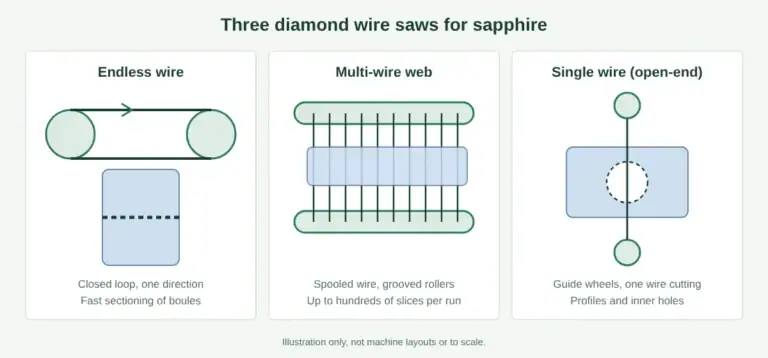
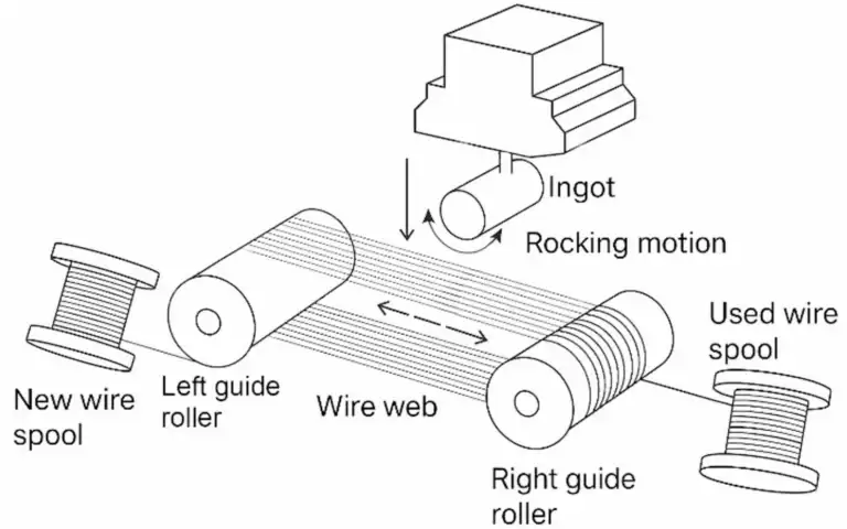
A machine concept should be tested using material representative of the actual requirement. The oscillating multi wire saw is one option for equipment review. No numerical performance claim for a particular plane is established by naming that option.
Ask for a trial that records sapphire orientation, input geometry, output thickness, edge condition and downstream evaluation. If the project includes more than one plane, separate their results instead of reporting one combined yield without explanation.
Orientation language also appears in other crystal applications. The AT-cut quartz discussion provides a separate example of a functional crystal cut. Its angle conventions and material behaviour must not be transferred to sapphire.
Does correct thickness prove correct orientation?
A thickness map evaluates geometric uniformity. An orientation measurement evaluates the relationship to the lattice. Edge inspection and surface assessment answer still other questions. Define each acceptance feature explicitly so that one successful measurement is not used to imply that all requirements passed.
Sapphire orientation verification should be tied to the same slice identity used for thickness and finishing records. If only selected samples are measured, state the sampling basis. Do not present that sample result as a full-lot inspection.
After release, preserve the directional reference required downstream. Define packaging that protects both the surfaces and the traceability information, especially where visually similar wafers have different planes.
Make the Reference Transfer Auditable
Use a reference-transfer record alongside the dimensional drawing. It should show the original material mark, the mechanical feature used to locate it, and the identification applied after preparation. The record answers a simple question: can a second operator determine the intended plane without asking the first operator what the mark used to mean?
A sapphire orientation label can be lost before slicing begins. If a face is cropped or ground, decide which surviving feature carries the reference and how that relationship is checked. Do not assume that an external flat is a crystallographic datum simply because it is convenient for clamping.
Treat a requested angular offset as a complete instruction. Record the reference plane, direction, sign convention and the evidence used to establish them. An isolated angle is ambiguous when the fixture can be approached from more than one direction. Resolve that ambiguity on the drawing, before a correctly sized blank is cut on the wrong relationship.
Keep the qualification scope clear. A saw trial can provide dimensions and observations about the mounted assembly. It does not replace the method used to verify crystal orientation. If orientation measurement is outside the supplier’s scope, identify who performs it and how the result remains linked to the returned pieces.
The sapphire orientation inspection record should survive release and any selection of samples. If only part of the batch is checked, identify those positions. A certificate attached to an ingot should not be treated as proof that every later mounting operation preserved its reference correctly.
For a repeat job, compare the new reference scheme with the approved one. A change in the supplier’s marks or stock preparation may matter even when the plane name is unchanged. Document that change instead of allowing an operator to improvise a new convention that the receiving team cannot interpret.
A concise transfer package is sufficient: material identification, a marked drawing, the original and transferred reference, and the agreed verification method. These records are useful because they preserve meaning. Adding more plane terminology without those connections makes the enquiry longer, not clearer.
| Decision field | Evidence to retain |
|---|---|
| Incoming crystal | Plane record and original reference mark |
| Prepared stock | Surviving datum and transferred identification |
| Returned blank | Slice identity and orientation verification scope |
Choose the Page That Answers Your Question
This article answers: How can the required plane and direction survive preparation and mounting? It does not replace the following equipment or application scopes.
| Your question | Relevant page | Boundary |
|---|---|---|
| Need the sapphire slicing context? | sapphire slicing | Application or process context for the receiving task |
| Need the oscillating multi wire saw context? | oscillating multi wire saw | Equipment configuration and its stated scope |
| Need the AT-cut quartz discussion context? | AT-cut quartz discussion | Application or process context for the receiving task |
FAQ
Does correct thickness establish sapphire orientation?
No. Thickness and sapphire orientation are different requirements. A blank can meet its dimensional target while the reference relationship is wrong. Verify the plane under the agreed method and keep that evidence linked to the dimensional inspection.
Is a plane name sufficient for sapphire orientation?
Not always. Include any required directional reference or offset convention and show how it is located on the stock. The operator needs a usable relationship between the material record and the fixture, not only a name in the purchase order.
How is sapphire orientation retained when a mark is removed?
Transfer the reference under the approved procedure before removing it, and record the surviving feature. If that relationship cannot be established, stop and resolve the identity problem rather than guessing from the shape of the prepared piece.
What to Include in a Supplier Request
Provide the material certificate, named plane and indices, required orientation tolerance, any miscut and its reference, workpiece dimensions and the desired blank thickness. Identify the intended finishing condition and the inspection method used for acceptance.
A well-specified sapphire orientation request removes ambiguity before machining begins. It also makes a trial useful: the returned blanks can be checked against the same crystal and geometric requirements that the production route will use. That is more valuable than a general claim that one plane is easier, smoother or faster to cut.
Send the plane name and indices, any miscut with its axis and sign, the required tolerance and the method used to verify it. Mark how the reference will survive cropping, mounting and packaging. For a multi-plane project, inspect and report each sapphire orientation separately rather than combine every result into one yield figure.