For VCM and encoder magnets, thin NdFeB slice 0.3mm cutting is not just “making the magnet thinner.” At 0.3-1.0 mm thickness, a small change in wire tension, coolant flow, or fixture support can turn a good NdFeB block into warped slices, chipped corners, and a TTV result that fails before coating.
The short answer: 0.3 mm NdFeB slices need a fine diamond wire process, low cutting force, stable workholding, and inspection focused on TTV, Ra, edge chipping, and kerf-to-slice ratio. A general magnet slicing setup may cut 2-5 mm parts all day, but it often struggles once the finished slice becomes thinner than the kerf of a conventional ID saw.
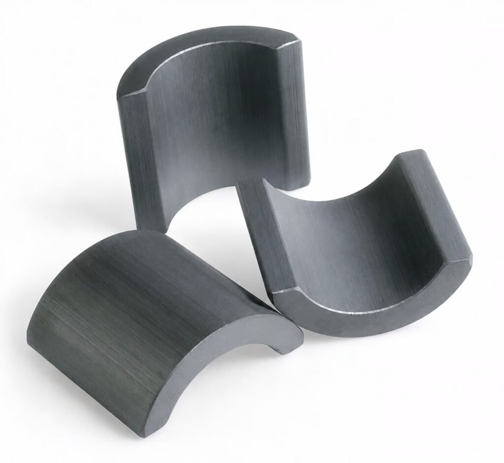
Where 0.3-1mm NdFeB Slices Are Used
Most thin NdFeB slice production goes into compact assemblies where magnetic force is needed inside a very small mechanical envelope. The common examples are VCM actuators, magnetic encoders, micro servo motors, miniature sensors, consumer electronics modules, and small medical or optical positioning systems.
In a VCM actuator, a magnet slice may be only 0.3-0.8 mm thick, but thickness variation still affects force constant and coil gap. In a magnetic encoder, the same kind of variation can show up as uneven signal amplitude after magnetization. That is why this article stays narrow: thin NdFeB slice 0.3mm cutting for 0.3-1.0 mm parts, not general block slicing or full equipment selection.
| Application | Typical Slice Thickness | Main Concern |
|---|---|---|
| VCM actuator magnets | 0.3-0.8 mm | Thickness consistency and edge chipping |
| Magnetic encoder rings or strips | 0.5-1.0 mm | Flatness and magnetization stability |
| Micro servo motor magnets | 0.6-1.0 mm | Batch repeatability |
| Sensor magnet wafers | 0.3-0.6 mm | Kerf loss and handling damage |
For broader machine selection across 0.3-3 mm, large blocks, SmCo, ferrite, and multi-wire throughput planning, use the dedicated magnet slicing machine hub. This blog only covers the thin-slice process window.
The Challenges of Thin Slicing
NdFeB looks like a metal on the drawing, but in cutting behavior it acts closer to a brittle ceramic with magnetic handling problems. A sintered NdFeB block is hard, low in fracture toughness, sensitive to local heat, and easy to chip at the exit side of the cut. When the target part is 0.3 mm thick, there is almost no thickness margin left for later grinding.
One thing that trips factories up is clamping. A fixture that works for 2 mm slices can be too aggressive for 0.3 mm parts. If the block is supported only at the bottom, the last 20-30% of the cut may vibrate, especially near the exit edge. If the clamping pressure is too high, the first few slices look fine, then the remaining block relaxes and the thickness starts drifting.
The second issue is swarf. NdFeB cutting produces fine magnetic particles that stick to the wire, guide rollers, fixtures, and slice surfaces. If coolant filtration cannot keep fine particles below roughly 10-20 μm from recirculating, those particles become loose abrasive. The result is a worse Ra value and random scratches that are hard to explain from feed rate alone.
Fair warning: 0.3 mm samples are often easier than 0.3 mm production. In a sample run, the operator can slow everything down and inspect every slice. In production, wire wear, coolant temperature, and fixture loading create drift over hours. The process has to be stable, not just lucky.
TTV / Surface Finish / Kerf-to-Slice Ratio
For thin NdFeB slice 0.3mm cutting, three numbers matter more than headline cutting speed: TTV, Ra, and kerf-to-slice ratio.
TTV, or total thickness variation, tells you whether the slice is usable before coating or lapping. For 0.3-0.5 mm NdFeB slices, a realistic process target is often TTV within 10-20 μm after slicing, depending on downstream grinding allowance. Tighter values are possible, but the cost shows up in slower feed, finer wire, stricter fixture control, and more inspection time.
Ra controls coating quality and assembly friction. Research on NdFeB diamond wire sawing shows that feed rate and wire speed strongly affect surface roughness, with lower feed and higher wire speed generally improving surface quality. Two useful technical references are this NdFeB diamond wire sawing study in Micromachines and a related NdFeB sawing process paper in Materials.
The kerf-to-slice ratio is where 0.3 mm gets painful. If you use a 0.30 mm wire and get a 0.35 mm kerf, the process removes more material than the finished 0.3 mm slice thickness. That is a poor yield equation for rare earth magnets.
| Target Slice | Typical Diamond Wire Kerf | Kerf-to-Slice Ratio | Process Meaning |
|---|---|---|---|
| 1.0 mm | 0.25-0.35 mm | 25-35% | Manageable production window |
| 0.6 mm | 0.20-0.30 mm | 33-50% | Fine wire becomes important |
| 0.3 mm | 0.13-0.22 mm | 43-73% | Ultra-fine wire and low force required |
This is why thin NdFeB slice 0.3mm cutting should not be evaluated by cut completion alone. A process that “cuts successfully” but wastes 60% of the block in kerf dust is not economically acceptable unless the part value is very high.
Recommended Equipment for 0.3-1mm NdFeB Slices
For this thickness range, Vimfun usually evaluates two machine directions: SOM2-600S for high-speed ultra-thin slicing and SOMS3-430S for more difficult materials or shapes that benefit from controlled oscillation.
| Model | Best Fit | Typical Reason to Choose |
|---|---|---|
| SOM2-600S | 0.3-3 mm thin slices, high-speed production | High wire speed, stable thin-slice throughput |
| SOMS3-430S | Harder or more sensitive thin-slice jobs | Oscillating cut helps reduce cutting force and edge damage |
| SOM4-630D | Standard block slicing above the ultra-thin range | Better for volume slicing of thicker parts |
In our experience, SOM2-600S is the first model to test when the customer wants repeatable 0.3-1.0 mm sheets from rectangular NdFeB blocks. SOMS3-430S becomes more attractive when the magnet grade is brittle, the block shape is less friendly, or the edge-chipping limit is tighter than normal.
For robot and servo motor magnets, the thin-slice decision often connects to motor torque density and encoder package size. For application-level requirements in robotic axes and compact servo drives, see robot servo motor magnet processing.
Process Parameters for Thin NdFeB Slice 0.3mm Cutting
Start with conservative parameters, then open the process window only after TTV and chipping are stable. A practical starting point looks like this:
| Parameter | Starting Range | Why It Matters |
|---|---|---|
| Wire diameter | 0.10-0.20 mm | Controls minimum kerf and material loss |
| Feed rate | 0.05-0.25 mm/min | Reduces cutting force and exit chipping |
| Wire speed | 1,000-1,800 m/min | Improves abrasive engagement and surface finish |
| Coolant temperature | 20-25°C | Limits thermal drift across long runs |
| Filtration | 10-20 μm | Prevents magnetic swarf from scratching slices |
| Slice allowance | 20-50 μm | Gives room for light lapping or coating prep |
Do not copy these numbers blindly. NdFeB grade, block size, magnetization state, coating requirement, and fixture design all change the final recipe. We tested this and found that a 0.15 mm wire can look excellent on a 20 mm cutting height but become unstable on a taller block if wire span and coolant access are not controlled.
The fixture is part of the process, not an accessory. For 0.3 mm slices, we prefer broad-area support, low clamping stress, and a sacrificial backing layer at the exit side when edge quality is critical. The backing layer slows handling, but it can save a batch when the customer rejects any visible corner breakout.
Coolant management also matters more than people expect. NdFeB swarf should stay wet and controlled. Letting magnetic dust dry in trays or around the wire path creates both safety and quality problems. A wet collection system, magnetic separation, and regular coolant concentration checks are basic operations for this kind of job.
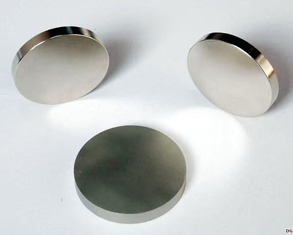
Quality Inspection
A thin-slice job should not pass inspection just because the parts separate cleanly. The inspection plan needs to catch thickness drift, surface damage, and process instability before coating.
Use a simple but disciplined flow:
- Measure slice thickness at 5-9 points per part, depending on part size.
- Calculate TTV and track it by slice order from the block.
- Check Ra on both entry and exit faces, not only the cleaner face.
- Inspect edge chipping under magnification, especially at the exit side.
- Weigh sample slices and estimate kerf loss against theoretical yield.
- Record wire life, coolant temperature, and feed rate for the batch.
For 0.3 mm slices, we also like to keep the first, middle, and last slices from each block as process witnesses. If the middle slice is good but the last slice drifts, the problem is usually fixturing, wire wear, or block relaxation. If all slices drift together, look at wire tension, guide roller alignment, or coolant temperature.
The rejected option here is “cut fast, then fix it in lapping.” That works for thicker magnets. For 0.3-0.5 mm NdFeB, aggressive post-processing can bend parts, round edges, or remove too much material. The better route is to hold the slicing process close enough that finishing becomes a light correction, not a rescue operation.
If you are developing VCM, encoder, or micro servo magnet slices in the 0.3-1.0 mm range, send the magnet grade, block size, target thickness, TTV limit, Ra requirement, and monthly volume. Vimfun can review whether SOM2-600S or SOMS3-430S is the better first test route and prepare a sample-cut plan.