
Wafering: From Crystal Ingot to Finished Wafer
Wafering does not end when the wire clears the ingot. A batch of intact blanks can still fail at lapping because a thin region leaves no stock to remove the damaged surface. Set the blank thickness with the finishing team first; then choose the cutting setup.
The three handoffs that deserve the most attention are crystal-to-fixture, saw-to-release and blank-to-finishing. Each can lose either material or reference information. Following those handoffs is a better way to specify a wafering line than asking one supplier to guarantee a finished substrate from a nominal slice thickness.
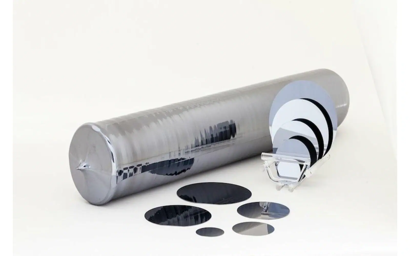
What Does Wafering Include?
The term usually covers turning bulk crystal into wafer form, with the precise boundary depending on the supplier's scope. It does not mean fabrication of transistors or packaging of finished chips. A line quotation should identify whether crystal growth, cropping, surface finishing and final inspection are included rather than treating every operation as part of one machine.
For a basic definition of the substrate, see this wafer reference. The useful engineering distinction is between the wafer's intended function and the condition in which it leaves a particular process. An as-cut blank and a polished substrate can share a diameter while having very different acceptance requirements.
Which crystal information must reach the saw?
The first wafering decision is what the finished substrate must support. Material, crystal form, orientation, diameter and electrical requirements belong on the input specification. A photograph of a round ingot does not establish any of those properties. Obtain the supplier's material identification and keep its lot number attached to the work order.
Crystal growth determines the starting material; slicing cannot correct the wrong crystal orientation or remove every growth defect. Equipment for this upstream stage is discussed on the 結晶成長炉 page. Define the transfer condition between growth and machining, including the information available on usable length and sections that must be excluded.
In wafering trials, an unusually clean sample should not silently become the baseline for a production lot. Record whether the supplied piece represents normal stock, an experimental composition or a selected section. That context is needed when interpreting later breakage or finishing results.
Crop, Identify and Establish Reference Surfaces
Before slicing, the operator needs stable surfaces for locating and holding the workpiece. Cropping removes or separates sections according to the approved material plan. External shaping establishes the geometry needed by the fixture and downstream process. Neither operation should be justified merely because the saw can accommodate the largest available block.
Keep orientation information legible after preparation. If the identifying mark will be removed, transfer the reference by an approved method before machining. Make the datum scheme part of the drawing: the axis used to align the ingot, the intended wafer plane and the location from which thickness will be measured.
This preparation stage also establishes a wafering material balance. Record incoming mass or dimensions, usable section, cropping allowance and planned slices. Without those boundaries, a reported improvement in saw yield may simply reflect a different starting section rather than a better cut.
Keep three identifiers on the traveller: the original ingot lot, the prepared section and the slice position. If one ingot becomes two mounted sections, give the sections separate identities before the first mark is removed. Otherwise, a thickness trend from one section can be mixed with a material observation from the other.
For wafering, I would reserve a photograph for the datum transfer rather than fill the report with general machine pictures. Show the original reference and the feature that locates it on the fixture. The pitfall is treating a convenient external face as the crystal datum. They may coincide, but that relationship must be established rather than guessed.
A useful wafering record has separate fields for as-cut thickness, thickness after mechanical finishing and final thickness. Leave an unmeasured field blank. Copying the final value into all three fields erases the evidence needed to identify which operation changed the geometry.
The blank is not the finished wafer.
Mount the Ingot without Losing the Datum
Mounting must support the crystal through entry, the main cut and final separation. An apparently rigid assembly can still place stress into a brittle workpiece or interfere with coolant access. Fixture assessment should therefore consider the whole operation rather than only whether the ingot fits on the table.
Specify how the material will be released after cutting. Where a bonding system is used, its compatibility and release procedure belong to the approved process documentation. Do not select an adhesive from a general internet recipe. The material supplier, fixture design and local handling requirements may impose different conditions.
A useful wafering setup record includes photographs of the mounted workpiece, the reference marks and the support arrangement. These are diagnostic records, not decorative images. If the final slices show a directional thickness trend, the mounting record helps distinguish an alignment issue from a cutting issue.
How much stock should the blank retain?
At the cutting station, translate the finished thickness into an as-cut target with the finishing team. Material removed by subsequent operations must be budgeted separately from the material lost in the cut. The drawing should state which thickness applies to the sliced blank and which applies to the finished wafer.
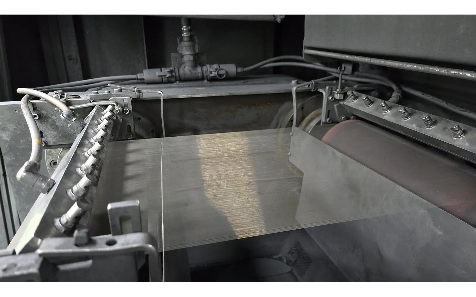
For the equipment stage, review the wafer slicing machine options against actual material, workpiece geometry and batch requirements. Multi-line production, individual research cuts and orientation studies do not necessarily justify the same setup. Wafering capacity should be compared using accepted blanks and the required downstream condition, not only nominal slices per cycle.
Record the order of slices within the ingot. Retaining that order makes it possible to investigate variation from the first slice to the last and to connect a finishing problem with a particular location in the original crystal.
Release, Clean and Protect the Blanks
Separation is a handoff, not an administrative step. Thin blanks can be damaged while being released, transferred or cleaned, even when the cutting operation was satisfactory. Define the handling method before the trial and reserve suitable trays or carriers for the incoming slices.
Keep debris from becoming a second source of surface damage. Cleaning chemistry, waste collection and any material-specific restrictions must follow the approved site procedure. A wafering trial should not substitute an improvised wash for a qualified cleaning step and then attribute every scratch to the saw.
Inspect enough material before and after release to understand where defects appear. A photograph taken only after cleaning cannot establish whether a chipped edge occurred during cutting, debonding or transport. Preserve the distinction in the test report.
Where does surface finishing change the result?
The finishing route depends on the substrate specification. Grinding, lapping, chemical treatment and polishing perform different functions and should not be described as interchangeable ways to make a wafer look shiny. The 研削およびラップ装置 page addresses the mechanical finishing stage.
For wafering procurement, agree on the measurement state: as-cut, after mechanical finishing or after final polishing. Define thickness sampling, edge exclusion, cleanliness and how the wafer is supported during measurement. A single central thickness reading cannot establish uniformity over the entire surface.
The final record should connect material lot, slice position, process history and inspection result. If a blank fails, that traceability supports an investigation rather than a dispute about which machine was responsible. Keep accepted yield, rework and rejects separate.
Build the Trial around the Process Handoffs
A practical wafering trial starts with a short acceptance sheet. Identify the material and input geometry; state the required blank thickness and finishing allowance; list the defects that matter; and agree on who measures the output. Then document the actual process condition and return enough samples for independent inspection.
Ask the receiving operation what makes a blank difficult to process. The answer may be an edge defect, contamination, a thickness trend or insufficient stock for finishing. Those details are more useful than an unrestricted request for the highest possible cutting speed.
Wafering is successful when each stage supplies the next with the correct material, geometry and evidence. The aim is a predictable route to accepted substrates. A fast cut is valuable only when its blanks can complete that route without an unplanned loss of material or quality.
Before a wafering trial, send the finishing team one sheet containing the intended plane, blank target, inspection area and reserved removal allowance. Ask it to approve that handoff. During the trial, retain slice order through release and measure representative blanks before any corrective finishing. That is the evidence needed to decide whether the next change belongs at the saw or downstream.