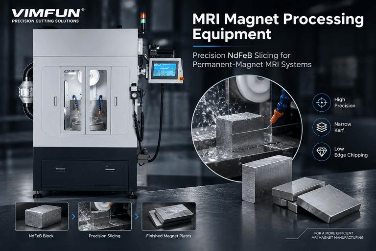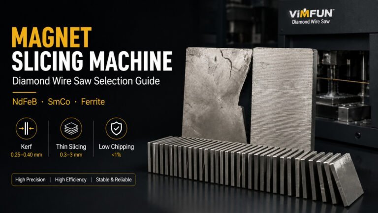
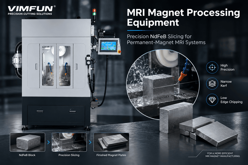
MRI magnet processing equipment for permanent-magnet systems must do more than cut a sintered NdFeB block to size. Vimfun’s core solution uses an endless diamond wire saw to produce repeatable dimensions with low cutting force, flexible part positioning, and a stable unidirectional cutting path. Grinding and lapping equipment then controls the final surface condition and batch consistency required for magnet-module assembly.
This distinction matters because not every MRI scanner uses the same magnet technology. High-field clinical systems commonly use superconducting magnets, while some low-field and open MRI systems use large permanent-magnet assemblies. Vimfun equipment supports the slicing, grinding, and polishing stages for the NdFeB or other permanent-magnet components used in the latter category. It does not manufacture superconducting coils or complete MRI scanners.
MRI Magnet Manufacturing Overview
A permanent-magnet MRI assembly is built from many magnetic blocks or plates positioned within a steel return yoke and pole structure. The magnetic design determines the material grade, magnetization direction, segment geometry, and placement of each component. Manufacturing then has to reproduce those physical parts consistently enough for the magnet integrator to complete assembly, shimming, field mapping, and system validation.
A typical component workflow is:
Sintered magnet block → precision slicing → grinding/lapping → cleaning → coating → dimensional and magnetic inspection → magnetization or assembly
The cutting stage establishes the basic geometry and material yield. Grinding and lapping then bring critical faces to final thickness, flatness, parallelism, and surface-finish requirements. Coating protects NdFeB from corrosion, while final inspection confirms that each part matches the engineering drawing and lot-control requirements.
The exact sequence varies by supplier. Some manufacturers cut unmagnetized blocks and magnetize later; others receive pre-oriented material and manage the parts according to the magnet integrator’s process. Equipment selection should therefore start with the complete manufacturing route rather than the finished part dimensions alone.
Precision Requirements for MRI Magnet Components
MRI image quality depends on the complete system’s field strength, stability, and uniformity. Magnet-component machining is only one contributor, but dimensional variation at the component level creates additional correction work during assembly and shimming. The correct processing target is therefore not a generic “medical-grade tolerance.” It is the tolerance and process capability defined by the customer’s drawing, magnetic model, and validation plan.
For equipment qualification, buyers should define:
| Exigence | Pourquoi c'est important | Processing Control |
|---|---|---|
| Thickness and TTV | Controls stack height and component position | Stable slicing allowance plus double-sided lapping |
| Flatness and parallelism | Supports repeatable bonding and assembly | Rigid fixturing and matched-face finishing |
| Edge integrity | Prevents cracks, chips, and coating discontinuities | Low-force diamond wire cutting and supported exits |
| État de surface | Affects cleaning, bonding, and coating preparation | Controlled grinding/lapping sequence |
| Lot consistency | Reduces variation across a magnet module | SPC records and serialized inspection data |
No equipment vendor should assign a universal tolerance without reviewing the part. Large blocks, thin plates, complex segments, and high-grade brittle NdFeB require different allowances and handling methods. First-article parts should be measured using the same datum scheme and inspection method that will be used during production acceptance.
For the upstream slicing stage, see our guide de sélection des machines de découpe d'aimants. For final thickness, TTV, and surface control, see the NdFeB magnet grinding and polishing workflow.
Specialty Considerations for Medical Magnet Production
Traceability and Process Validation
MRI scanners are regulated medical devices. The FDA identifies MRI systems as Class II medical devices in the United States, and IEC 60601-2-33 defines particular safety and essential-performance requirements for diagnostic MR equipment. A component-processing machine does not certify the completed scanner, but it should support the manufacturer’s quality system with repeatable recipes, controlled access, calibration records, alarms, and exportable production data.
ISO 13485 is the internationally recognized quality-management standard for medical devices. When processing equipment enters an ISO 13485-controlled supply chain, buyers commonly need documented installation and operating qualification, change control, maintenance records, and traceability from incoming material lot to finished component batch. The exact validation package must be agreed with the MRI manufacturer; compliance cannot be inferred from machine accuracy alone.
NdFeB Corrosion and Cleanliness Control
Freshly cut NdFeB is vulnerable to oxidation. Diamond wire slicing should use a compatible water-based coolant with corrosion inhibitor, followed by prompt cleaning and drying. Grinding slurry, loose particles, and residual process chemicals must be removed before coating or bonding. The line should separate dirty cutting operations from clean inspection and packaging areas.
Brittle Parts and Magnetic Safety
NdFeB is hard and brittle, so aggressive feed, poor support, or an unsupported wire exit can cause chipping and hidden cracks. Parts should be processed before magnetization whenever the approved manufacturing route permits. If magnetized components must be handled, fixtures, tools, guarding, and operator procedures need a dedicated magnetic-force risk assessment.
Measurement System Alignment
Micron-level specifications are meaningful only when the supplier and customer use aligned measurement methods. Temperature, datum selection, fixture pressure, instrument calibration, and sampling plan can all affect results. Approve the measurement method with the first article, then retain the same method for production lots.
Recommended MRI Magnet Processing Equipment
Most permanent-magnet MRI component lines need two complementary equipment stages rather than one universal machine.
Why Use an Endless Diamond Wire Saw for MRI Magnets
An endless diamond wire saw uses a closed diamond-coated wire loop that travels continuously in one direction. Because the wire does not reverse at the end of each stroke, the cutting condition remains stable across the workpiece. This is particularly useful for brittle, high-value NdFeB parts where edge damage, directional cutting marks, and repeated setup changes can undermine first-article yield.
For MRI magnet components, the main advantages are:
- Low cutting force: Distributed diamond contact reduces the concentrated mechanical load that can chip brittle sintered magnets.
- Unidirectional cutting: Continuous one-way wire motion avoids the reversal marks associated with reciprocating systems and supports a more consistent cut face.
- Flexible geometry: Single-loop equipment can cut individual blocks, plates, reference faces, angled sections, and—when paired with rotary or multi-axis motion—selected contours and segmented geometries.
- Fast changeover: The machine can move between prototype or small-batch geometries without rebuilding a multi-wire web, which suits medical development and qualification work.
- Cleaner process options: Fixed diamond abrasive eliminates loose-abrasive slurry. Depending on the magnet material and cleanliness plan, the system can use controlled coolant with filtration and corrosion inhibitor.
The trade-off must also be stated clearly. Endless diamond wire normally has a wider kerf than ultra-fine reciprocating or multi-wire systems. Its value for MRI magnets is not “the smallest kerf of every wire technology”; it is the combination of speed, stable one-way motion, simple changeover, and geometry flexibility. When the job is thousands of identical thin plates, a multi-wire saw may deliver better throughput and material yield. When the job is a high-value prototype, a short medical batch, a thick block, or a geometry requiring flexible positioning, the endless wire saw is often the better first process to evaluate.
Vimfun can configure the endless-wire platform as a standard single-wire slicer, a scie à câble diamantée rotative for indexed or circumferential positioning, or a 4-axis CNC diamond wire saw for controlled multi-axis paths. The correct configuration depends on the drawing and should be proven by a sample cut.
Endless-Wire and Multi-Wire Slicing Options
Use an endless diamond wire machine to produce individual parts, qualification samples, thick sections, or geometries that need rotary or CNC positioning. Use a multi-wire aperçu des machines de découpe d'aimants when the requirement is high-volume production of many identical parallel plates from one NdFeB block. Machine capacity should be selected by maximum block envelope, cut depth, slice thickness, geometry, and production volume—not by the word “MRI.”
For thin parts, bonded support and conservative feed help control exit chipping and deformation. For larger blocks, wire tension stability, coolant delivery, and automatic feed adjustment become more important. In both routes, actual wire diameter, speed, tension, feed, and coolant settings must be qualified against the supplied NdFeB grade rather than copied from a generic parameter table.
Double-Sided Lapping and Polishing
Use double-sided lapping when both faces must achieve controlled thickness and parallelism across a batch. The correct platform depends on part size and throughput:
| Production Need | Recommended Configuration | Meilleur ajustement |
|---|---|---|
| R&D and first-article trials | Endless diamond wire saw + 13B-6LY/P lapper | Flexible sample cutting and process qualification |
| Angled, indexed, or selected contour cuts | Rotary or 4-axis endless diamond wire saw | Low-volume complex components |
| Mid-volume component production | SOM4-630D slicing platform + 16B-5LY/P lapper | Standard NdFeB plates and blocks |
| Higher-volume finishing | Multi-wire slicing + 22BF-5LY/P lapping/polishing | Repeated batches requiring tighter process control |
Final configuration should include coolant filtration, corrosion control, guarded slurry collection, recipe management, and an agreed inspection package. Optional automation should be justified by lot size and handling risk; it should not replace first-article validation or in-process sampling.
Vimfun Capabilities
Vimfun can configure the slicing and finishing stages around the customer’s magnet material, component drawing, production volume, and inspection requirements. A technical review should cover:
- Magnet grade, block dimensions, and supplied condition
- Finished geometry, tolerances, datums, and surface requirements
- Cutting allowance, coating route, and cleaning restrictions
- Batch size, annual volume, and traceability requirements
- Required first-article report and production data format
The recommended starting point is a sample-processing trial. Send representative material and a controlled drawing. We can evaluate the cutting route, produce sample parts, measure the agreed characteristics, and use the results to define a production-ready equipment configuration.
Request Medical-Grade Consultation
FAQ
Does this equipment manufacture the complete MRI magnet?
No. It processes permanent-magnet blocks or components used by qualified magnet and MRI system manufacturers. Magnet assembly, shimming, field mapping, system integration, and regulatory validation remain with the magnet-system manufacturer.
Is permanent-magnet processing relevant to every MRI scanner?
No. Many high-field clinical MRI systems use superconducting magnets. This page applies to permanent-magnet MRI architectures, including certain low-field and open systems, and to their NdFeB component-processing requirements.
Can one machine complete both slicing and final finishing?
Normally no. Diamond wire slicing establishes geometry efficiently; grinding or double-sided lapping controls final thickness, parallelism, and surface condition. A qualified line combines the appropriate stages.
What information is required for equipment selection?
Provide the material grade, incoming block size, finished drawing, tolerance and datum scheme, surface requirements, batch volume, downstream coating route, and required inspection records.
External references:
[1] FDA — MRI Information for Industry: https://www.fda.gov/radiation-emitting-products/mri-magnetic-resonance-imaging/mri-information-industry
[2] IEC 60601-2-33:2022 — Medical electrical equipment, magnetic resonance equipment: https://webstore.iec.ch/en/publication/67211
[3] ISO 13485:2016 — Medical devices quality management systems: https://www.iso.org/standard/59752.html