Aluminiumoxid-Schneiden: Drahtsäge, Diamantscheibe oder Laser?
Alumina cutting method selection depends on part shape, material grade and finishing. Compare wire, blade and laser using a representative trial.
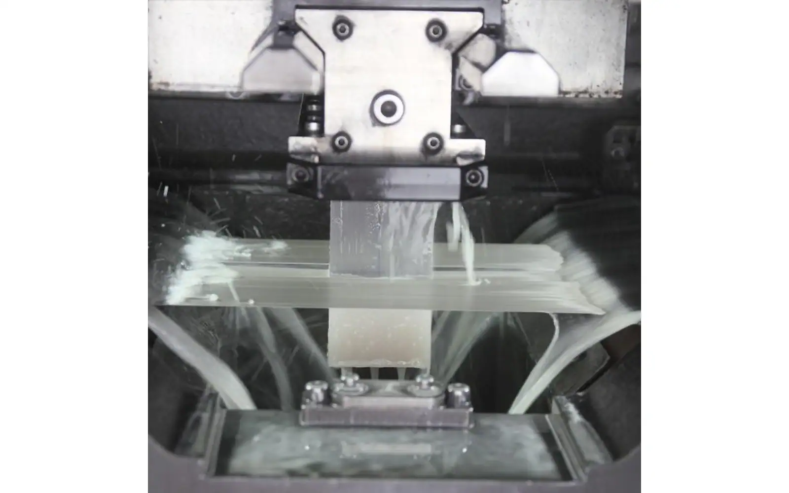
Alumina cutting for a stack of parallel plates is a different job from producing one cutoff or a localized feature. For repeated plates, I would assess a multi-wire setup first. For an individual straight separation, assess the blade route; for a specified feature, ask what the proposed laser process actually delivers.
That recommendation is about geometry, not a universal speed ranking. Alumina cutting still has to leave enough stock for finishing, and the blanks must survive release. A method that separates the block but loses the plates at detachment has not completed the job.
Vimfun SOM200 lists alumina among its applications and offers one small-format batch-slicing reference. For larger stock, the Vimfun SOM400 reference concerns repeated blank separation. Neither catalogue entry replaces a trial on the actual grade and receiving requirement.
Which stock does your alumina cutting job use?
Start with the material supplier's grade identification and incoming condition. Density, composition and processing history can differ among materials sold as alumina. Do not assign every sample the same behaviour based on its colour or an unspecified hardness chart.
Die aluminium oxide reference provides material background. For machining, the customer's actual grade and drawing are more useful than a general chemical description. State whether the workpiece is a block, plate, rod or another defined shape.
Are you making plates or individual features?
Cutting alumina into repeated plates presents a different task from cutting alumina ceramic along a single trim line or creating a local feature. Alumina ceramic cutting should therefore be specified by the required output: parallel blank production, an individual separation, or a defined feature. Compare wire sawing, diamond blades and laser processing against that task rather than ranking them for every alumina part.
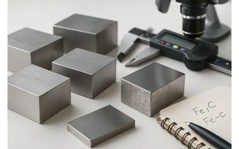
Repeated parallel plates, individual straight cuts and localized features place different demands on equipment. Consider the complete stock-to-part layout before comparing tools. The number of usable parts depends on retained geometry as well as cutting width.
For alumina cutting into repeated blanks, identify the required thickness and batch quantity. For an individual cut, specify the reference faces and permitted access. For a feature, show its shape and the condition expected at the boundary.
Die technical ceramic cutting application page concentrates on plate and substrate production from blocks. Keep that boundary clear when requesting a machine assessment.
Multi-Wire Sawing for Repeated Plates
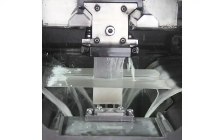
A guided wire web establishes repeated cutting positions and can form multiple blanks from one mounted workpiece. This is a useful concept when the requirement is a series of parallel plates rather than a sequence of unrelated features.
Alumina cutting on a multi-line system still requires suitable mounting, support through separation and a qualified release procedure. Tool condition and effective cutting width affect recovery, while the receiving operation determines how much finishing stock is needed.
Review the Doppelplatten-Mehrdrahtsäge for larger batch arrangements and the kleine Mehrdrahtsäge for smaller-format work. Their product positioning does not establish a trial result for your grade.
The SOM200 introduction lists a 200 × 200 × 200 mm workpiece envelope and 0.3–12 mm slices. The SOM400 information lists a cross-section up to 400 × 400 mm, length up to 830 mm and 1–35 mm slices. Both identify alumina in their application information. These are model references; they do not qualify every alumina grade at every listed thickness.
For alumina cutting, I'd choose the trial model from the mounted stock and required blank, not simply pick the larger envelope. The smaller setup may be enough for a research batch, while a larger charge requires assessment of support and release as well as capacity.
One source issue deserves attention: the SOM400 document gives inconsistent wire-diameter descriptions. No diameter recommendation is made here. Confirm that item in the technical agreement before selecting consumables for alumina cutting; copying whichever number looks more attractive is not a defensible choice.
The larger machine is not automatically the right trial.
Diamond Blades for Individual Cuts
A rigid blade arrangement can be useful where the task is a defined individual separation and the fixture provides appropriate access and support. The blade, its cutting system and the workholding must be selected for the actual material and geometry.
Compare alumina cutting with a blade using measured output rather than a generic assumption that a rigid tool always creates better dimensions. Effective cutting width, edge condition and finishing demand should be documented for the selected process.
The blade route may involve different setup and material-loss considerations from a wire web. A fair comparison includes the total requirement: how many cuts are needed, how the parts are held and whether the process supplies the intended blank condition.
Laser Processing for Defined Features or Separation
Laser processing uses a different energy interaction from abrasive removal. Its suitability depends on the material, thickness, feature and chosen laser process. The word “laser” alone does not describe the equipment or output condition.
For alumina cutting, ask how the proposed laser route will be evaluated for boundary geometry, cracks and any thermally modified region relevant to the component. Do not claim that all laser methods eliminate damage or that every laser process has the same limitation.
If the project compares laser and abrasive routes, provide identical part requirements and a common inspection plan. A successful feature in a thin test plate should not be presented as proof of repeated thick-block plate production.
Are the samples as-cut or already corrected?
As-cut, cleaned and finished parts should keep their labels. A polished plate cannot fairly represent an as-cut result unless the polishing effort is included. Establish the stock removal and time required by the receiving operation.
Alumina cutting comparisons should include thickness or feature geometry, edge condition, surface assessment and accepted yield. State whether internal damage is examined and how. A visually smooth surface does not prove the absence of subsurface flaws.
NIST's ceramic fracture research provides background on why machining defects need appropriate examination. For a specific failure, preserve the specimen and process history so that an investigation can distinguish cutting damage from release or handling damage.
Design Workholding for the Entire Operation
The fixture must support the material as the cut develops and parts become separated. Access for the cutting system and fluid management also belongs in the design. A setup that locates a solid block securely may behave differently after that block is divided.
For alumina cutting, plan how blanks will be detached, cleaned and transferred before the trial. Record any bonding system and its approved release procedure. Do not choose an adhesive or cleaning chemistry from an unrelated material example.
Track the timing of defects. Compare accessible features before release with the final condition, and retain rejected pieces. That evidence can prevent a handling issue from being misdiagnosed as a method-selection problem.
Evaluate Material Recovery and Process Effort Together
A narrow cut is valuable only if the resulting parts are usable. Count accepted output after the agreed inspection and include finishing removal, end allowances and rejects in the material balance. State whether recovery is measured by mass, volume or piece count.
Alumina cutting economics also include setup, consumables, interrupted runs and the effort needed downstream. An approach that removes less material at the cutting station may require more correction later. Conversely, a slower cut can be useful when it improves accepted recovery.
Avoid assigning generic cost or speed rankings to the three methods without actual project data. Describe the comparison boundary and request evidence for the proposed workpiece.
Compare the Job before Comparing the Tools
Draw the required intermediate product before selecting the method. A block divided into parallel blanks, a single cutoff and a local feature place different demands on the operation. A comparison that ignores those differences may reward a tool for a task the component does not require.
For alumina cutting, give each candidate the same starting-stock definition and delivered-state requirement. Identify whether its samples are as-cut or already corrected. If one method includes grinding and another does not, report the difference explicitly rather than attributing all of the final surface quality to separation.
Use a process comparison table with open questions, not unsupported rankings. Record the accessible cut geometry, support arrangement, release method and receiving checks for each candidate. A question such as whether the blank can be released intact is actionable. A general claim that one method is superior is not useful without the conditions that make it true.
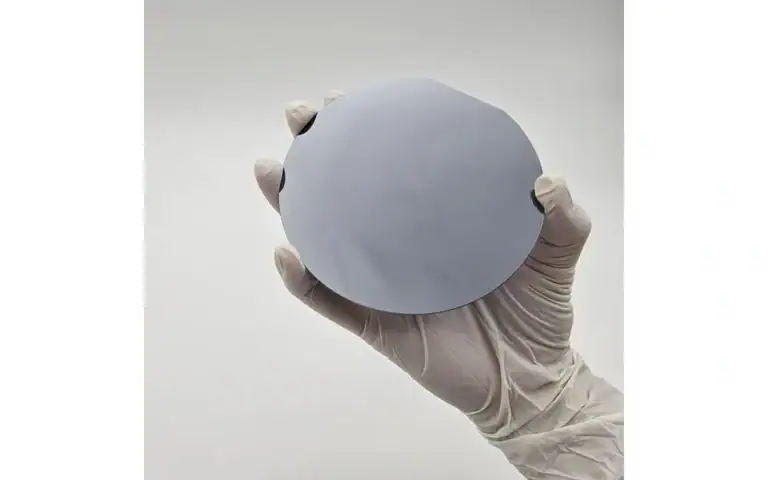
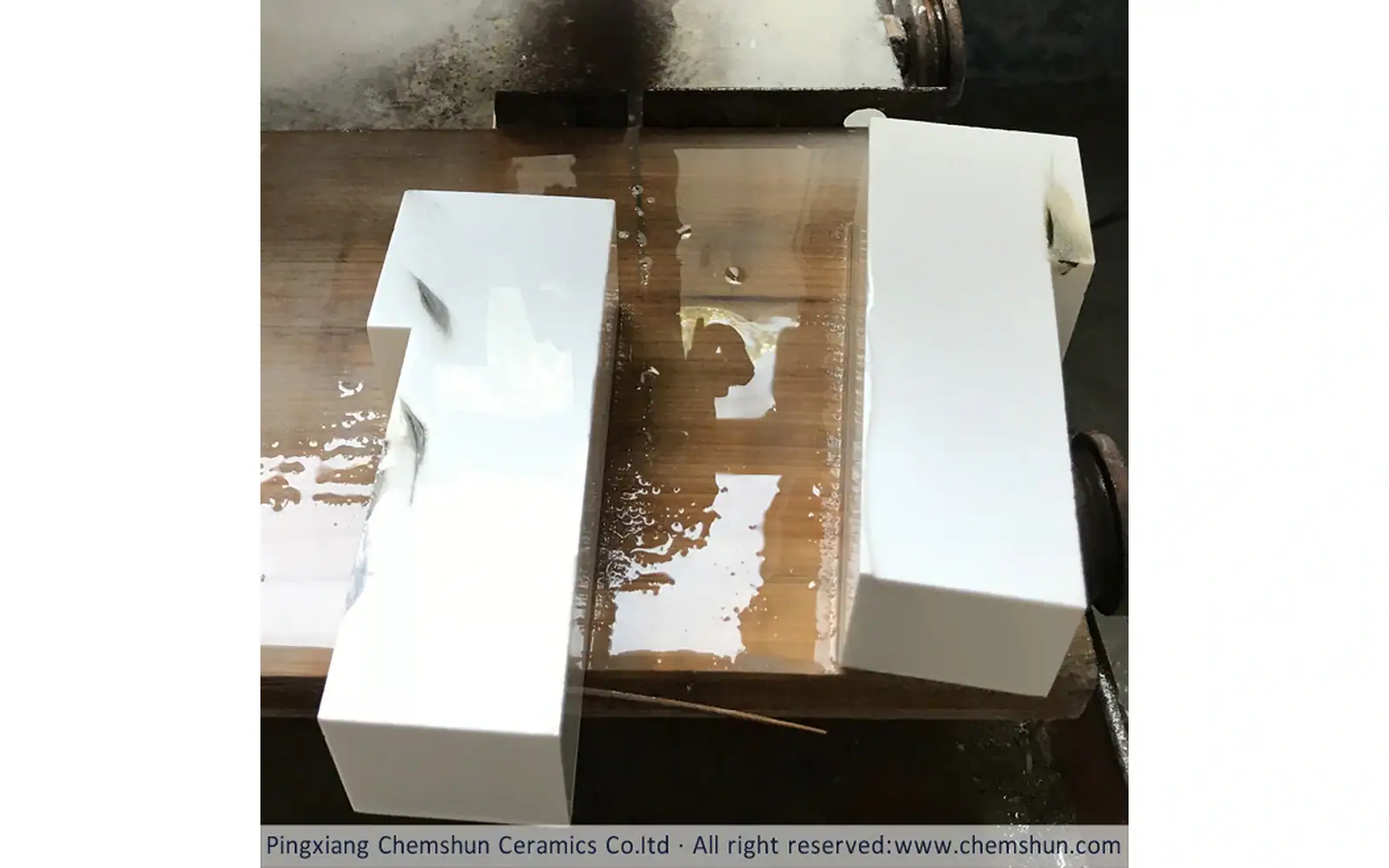
The alumina cutting trial sample must represent the stock being purchased. Keep the grade identification and preparation state with it. A photograph of a white plate does not identify its material or establish how the plate was made. A supplier’s selected sample can start a discussion, but the order drawing should define what later production must deliver.
Alumina cutting should be evaluated through the release boundary. Document which surfaces remain attached, where support is required and when the edge inspection takes place. If damage is first recorded after handling, investigate that handoff instead of immediately changing the cutting settings.
Keep correction stock visible in the material balance. A method with a narrower separation region may still require a different amount of subsequent removal. Accepted recovery depends on the whole specified route, so compare the retained blank condition as well as the apparent width of the cut.
For a first enquiry, send the actual geometry and ask each supplier to identify its qualification scope. Use the answers to choose a representative trial. The decision should explain why the method fits this task and what remains unverified; it should not turn an equipment preference into a promise for every alumina part.
| Entscheidungsfeld | Zu behaltende Beweise |
|---|---|
| Repeated plates | Batch arrangement and release of parallel blanks |
| Individual cut | Access, support and output geometry |
| Final feature | Correction steps and accepted surface condition |
Wählen Sie die Seite, die Ihre Frage beantwortet
This article answers: Which method fits the required geometry and receiving condition? It does not replace the following equipment or application scopes.
| Ihre Frage | Relevante Seite | Grenze |
|---|---|---|
| Need the technical ceramic cutting context? | technical ceramic cutting | Anwendungs- oder Prozesskontext für die empfangende Aufgabe |
| Need the dual plate multi wire saw context? | Doppelplatten-Mehrdrahtsäge | Ausrüstungskonfiguration und ihr angegebener Umfang |
| Need the small multi wire saw context? | kleine Mehrdrahtsäge | Ausrüstungskonfiguration und ihr angegebener Umfang |
FAQ
Is multi-wire separation always preferred for alumina cutting?
No. Alumina cutting method selection starts with the geometry. A multi-wire arrangement is a candidate for repeated parallel blanks; a localized feature or individual separation requires its own comparison. Confirm the complete receiving condition before choosing.
Does an attractive sample establish alumina cutting quality?
A photograph can show visible condition, but it does not establish every relevant defect or the stock required for finishing. Use the inspection method specified by the receiver and record whether the sample has already been corrected.
Which inputs make an alumina cutting trial useful?
Provide grade identity, stock dimensions, the intermediate blank drawing and the inspection boundary. State how release and later finishing will be assessed. The same requirements should be used when comparing wire, blade and laser proposals.
Prepare a Representative Trial
Send material identification, measured input geometry, output drawing, thickness or feature requirement, finishing allowance and acceptance method. Make clear whether the sample represents production material. If the eventual workpiece is larger, record the scale limitation of the trial.
Send the alumina grade, measured block drawing, plate thickness and finishing allowance. Select the first trial by geometry: repeated parallel plates, individual separation or a defined feature. Measure the returned blanks before corrective finishing and inspect again after release. Use accepted plates, not nominal count, to choose the alumina cutting route.