Silicon · slicing and blank preparation

Silicon Ingot Slicing

Choose a cutting route from your silicon blank, target slice thickness and downstream finishing requirements. Compare inverted multi-wire slicing with dual-station squaring and slab cutting.

Thin slicesInverted multi-wire feedLonger blanksModel-specific capacitySquared ingotsDual-station evaluation
Silicon ingots and wafers for silicon ingot slicing
Silicon ingots and wafer examples. Material overview; not a model-specific cutting result.

Start with the required operation

What must happen before a slice becomes a finished wafer?

A silicon ingot slicing project should define both the incoming blank and the condition required after cutting. Separating material into slices does not complete the substrate manufacturing process. Keep cutting allowances and downstream acceptance requirements visible throughout equipment selection.

01 · PREPARE

Shape and orient the blank

Identify the incoming geometry, cut direction, reference surfaces and clamping arrangement. If the job is squaring an ingot or producing slabs, state that separately from thin-slice production.

02 · SLICE

Make parallel cuts

A reciprocating wire web creates multiple parallel cutting paths. The roller arrangement, workholding and feed configuration must suit the blank and required slice range.

03 · FINISH

Prepare for final inspection

Allow for the specified grinding, lapping or polishing operations. Measure the output against the customer's thickness, surface and orientation requirements.

Here, wafer slicing means cutting the starting material into slices. A wafer sawing machine used to dice a processed device wafer performs a different job. Tell us which operation your enquiry concerns.

Silicon ingot slicing and finishing sequencePrepared silicon blank, parallel wire slicing, and downstream finishing shown as three separate stages. Concept only, not a machine layout.Prepared blankWire slicingFinishing
Process concept. Wafer shape, dimensions and final quality depend on the agreed application.

Mechanism and setup

How does silicon ingot slicing use an inverted wire web?

In the inverted configurations of SOMI2-600S and SOMI-430, the workpiece feeds upward into the cutting web. The machine coordinates wire travel with worktable feed. The mounting surfaces and available clearance need to be reviewed with the proposed blank.

Inverted feed describes the arrangement of the cutting operation. It does not, by itself, guarantee lower chipping, a particular thickness variation or a production rate. Validate the complete setup using representative silicon material.

Separate the cut pattern from the finished thickness

Roller groove spacing establishes the spacing of the cutting paths. Material removed in each cut and in later finishing affects the usable output. Do not calculate a guaranteed finished thickness from nominal wire diameter alone.

Record the selected wire, roller setup, feed program and measured cut result. The precision slicing inspection guide helps define the acceptance checks.

Cutting demonstration

Silicon Ingot Multi-Wire Slicing

See silicon ingot slicing with a diamond multi-wire saw. For a cutting trial, provide the ingot dimensions, crystal orientation and target slice thickness.

Watch on YouTube ↗
Silicon ingot slicing · Diamond multi-wire saw

Match the model to the job

Which silicon wafer slicing machine should you evaluate?

LONGER BLANK · THIN SLICES

SOMI2-600S

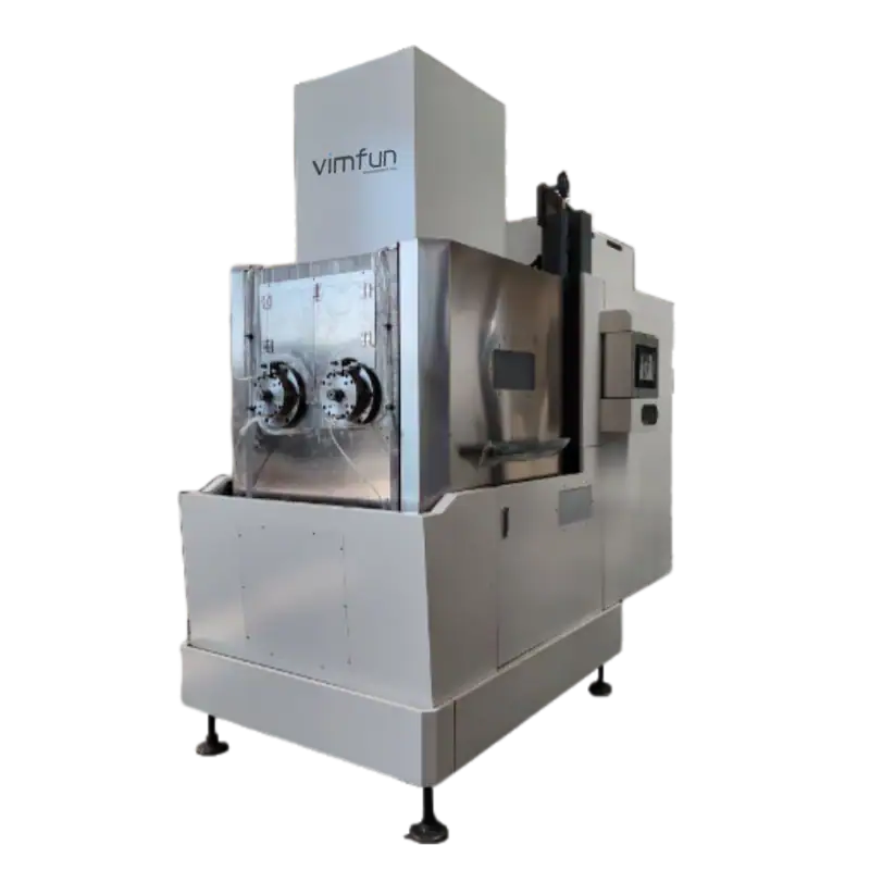
SOMI2-600S inverted multi-wire slicing machine
SOMI2-600S equipment view.

A two-spindle, single-station inverted multi-wire configuration with a listed 660 × 160 × 150 mm workpiece envelope and 0.3–3 mm slice range.

Evaluate this model when blank length exceeds the SOMI-430 range or when its higher listed maximum wire speed is relevant to a cutting trial. Maximum speed is not a guaranteed operating recipe.

View SOMI2-600S
SHORTER BLANK · THIN SLICES

SOMI-430

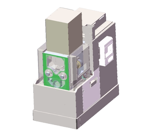
SOMI-430 inverted multi-wire saw illustration
SOMI-430 equipment illustration.

A two-spindle inverted multi-wire configuration with a listed 430 × 160 × 150 mm workpiece envelope and 0.3–3 mm slice range.

Compare this model when the shorter blank envelope fits the job. Review clamping, slice handling and the measured output before deciding whether the larger model is needed.

View SOMI-430
SQUARING · SLAB CUTTING

SOM4-630D

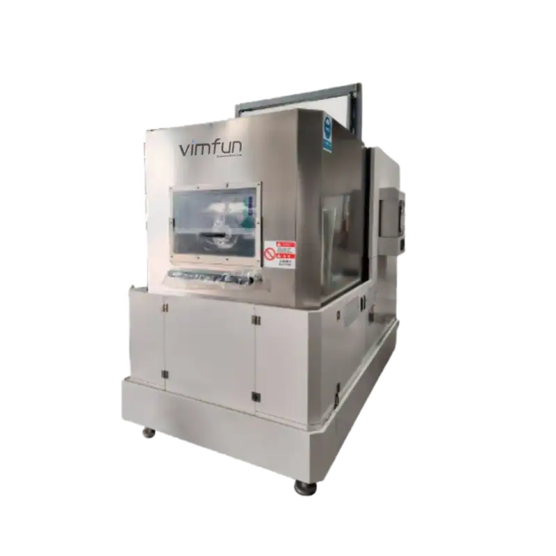
SOM4-630D four-roller dual-station multi-wire saw
SOM4-630D equipment view.

A four-roller tangential layout with two workstations. The documented silicon applications include ingot squaring and slab cutting, using a listed 630 × 160 × 150 mm envelope per workpiece.

Consider it for the blank-preparation task. Confirm slice range with the quotation; the two-station layout alone does not prove double the accepted output.

View SOM4-630D

Compare the listed capacities before requesting a trial

ModelWorkpiece envelopeListed slice rangeLayoutListed maximum wire speed
SOMI2-600S660 × 160 × 150 mm0.3–3 mmTwo-spindle, single-station inverted cutting2,200 m/min
SOMI-430430 × 160 × 150 mm0.3–3 mmTwo-spindle inverted cutting1,200 m/min
SOM4-630D630 × 160 × 150 mm per workpiece; two stationsConfirm for the specified applicationFour-roller tangential cuttingConfirm with the proposed configuration
These are machine specification values, not a validated silicon production recipe. The model number and rectangular workpiece envelope are not wafer-diameter ratings. Check the actual cross-section, orientation, fixture and motion clearance before selecting a model.

If your requirement falls outside these envelopes, submit the drawing before assuming compatibility. The multi-wire equipment overview provides the broader model range.

Measure accepted output

What should the silicon cutting trial measure?

Slice acceptance

  • Target cut thickness and the agreed measurement locations.
  • Thickness variation, edge condition and surface inspection criteria.
  • Orientation and reference-surface requirements.
  • Stock remaining for the specified finishing process.

Process and production inputs

  • Blank dimensions, condition and clamping arrangement.
  • Wire specification, roller setup and feed settings.
  • Cut time separated from handling and inspection time.
  • Accepted slice count, wire use and rejected-piece reasons.

When comparing a diamond wire saw for silicon, evaluate the usable output and finishing requirement together. A higher maximum wire speed, a thinner wire or an additional workstation is not enough to establish lower cost per accepted slice.

Keep the trial representative of the proposed production blank. A small sample can help evaluate a cutting approach, but it does not establish full-length throughput or repeatability for every geometry. Agree the trial scope and acceptance method before cutting.

For the downstream equipment category, see grinding and lapping equipment; confirm the material and finishing process separately. Silicon carbide uses a separate SiC slicing application guide.


Common equipment-selection questions

Is this a complete semiconductor wafer manufacturing line?

No. This page addresses cutting and blank preparation. Crystal growth, other shaping operations, finishing, cleaning and final qualification must be considered separately for the required product.

Does a 660 mm workpiece length mean a 660 mm wafer diameter?

No. The stated envelope is 660 × 160 × 150 mm. Check every dimension, the intended cutting orientation and the fixture clearance. A model name or one length cannot establish a wafer-diameter capacity.

Can the listed 0.3 mm slice limit be treated as the finished wafer thickness?

No. It is a listed cutting range. The finished thickness also depends on the specified downstream material removal and the accepted cut result. Confirm the requirement in the trial.

How do I choose between SOMI2-600S and SOMI-430?

Start with the incoming blank: compare the 660 mm and 430 mm listed lengths while checking the common cross-section limits. Then evaluate the required operating conditions and accepted output. The higher maximum wire speed does not replace a trial.

Why is SOM4-630D listed alongside thin-slice machines?

Its role here is silicon ingot squaring and slab preparation. It uses a four-roller, dual-station tangential arrangement and should be evaluated for that operation rather than assumed to share the thin-slice range of the inverted models.

Free sample cutting

Send your silicon blank and target slice requirements

Include incoming dimensions, material description, cut orientation, target thickness, finishing allowance and inspection criteria. State whether the job is squaring, slab cutting or producing a batch of thin slices.

Vimfun can review the SOMI2-600S, SOMI-430 or SOM4-630D route and discuss a representative trial. Confirm the sample arrangement, utilities and final equipment configuration with the team.

Request free sample cutting

CE certified · 12-month warranty · 12-hour response · Free sample cutting

Scroll to Top
Contact the Vimfun Team
Need a quote, support, or partnership discussion? Let’s connect.