
Vimfun SOM-220D · Four axes / Dual workstation
Магнитный многопроволочный станок SOM-220D
A magnet multi wire saw for straight-slice production. Four independently driven rollers and two work positions support parallel cutting of hard, brittle magnet blocks.
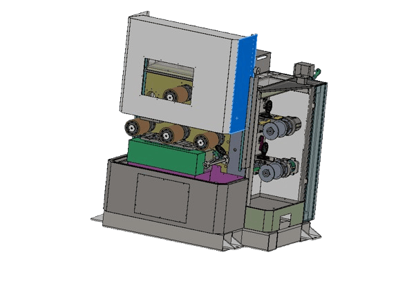
Where does SOM-220D fit in magnet machining?
The machine cuts prepared blocks into parallel straight slices. Its listed loading capacity is 220 × 220 × 150 mm at each of two positions. Review fixtures and holding layers as part of the usable envelope, then set the as-cut thickness with enough allowance for subsequent grinding or finishing.
Slicing is one stage in the finished-magnet route. The listed 2–8 mm thickness range is not a finished-part tolerance or a flatness guarantee. The NdFeB cutting and magnet machining guide places straight slicing alongside arc-segment production and downstream finishing.
How does a dual-workstation magnet multi wire saw operate?
Diamond wire travels from the pay-off spool through the grooved-roller system and onto the take-up spool. Multiple parallel wire spans create the slice pattern as the mounted material feeds into the web. The source specifies four independent roller drives and standard tangential cutting with two work positions.
Loading and cut-pattern illustration only; not a machine-routing drawing and not to scale.
Groove pitch sets the distance between neighboring cuts. Actual kerf removes material from that spacing, leaving the slice thickness. Do not treat wire diameter as measured kerf or calculate accepted slice count without allowing for end losses, holding requirements and finishing stock.
Two positions do not guarantee twice the output
The specification allows two material plates to be processed together. Compare complete cycles, including mounting, loading, cutting, unloading and inspection. Material mismatch and fixture preparation can affect the useful capacity.
Include wire-bow elimination time
Allow for the period needed to complete the cut through the remaining material as wire bow reduces. Its duration depends on the setup and material; the catalogue timing statement is not a guaranteed production cycle.
NdFeB and ferrite straight-slice applications
The product plan identifies NdFeB and ferrite magnet slicing as the main applications. The machine specification also lists ceramics and semiconductor materials as broader hard-and-brittle material categories. A successful recipe must be established for the actual grade rather than transferred solely because two materials share a category name.
| Приложение | Предоставляемая информация | Trial check |
|---|---|---|
| NdFeB magnet blocks | Grade, dimensions, material condition and whether the workpiece is magnetized | Edge damage, thickness consistency and finishing allowance |
| Ferrite blocks | Block geometry, support surfaces and target straight-slice thickness | Breakage, edge integrity and accepted slices per batch |
| Other ceramics or semiconductor materials | Exact material, incoming condition and required result | Material-specific sample cutting before selection |
When specifying an NdFeB multi wire saw or a ferrite slicing machine, separate the as-cut requirement from the finished drawing. For curved magnet segments, use the model comparison below; SOM-220D is positioned for straight slices.
Technical specifications
| Артикул | SOM-220D |
|---|---|
| Cutting arrangement | Four-axis tangential cutting; dual workstation |
| Maximum workpiece capacity | 220 × 220 × 150 mm × 2 |
| Толщина резки | 2–8 mm |
| Grooved roller material | High-molecular-weight polyethylene |
| Roller diameter | 170 ± 10 mm |
| Diamond wire diameter | 0.12–0.25 mm |
| Spool capacity | Up to 30,000 m |
| Reciprocating wire speed | Up to 800 m/min |
| Worktable lift stroke | Up to 180 mm |
| Spindle type | Cantilever spindle |
| Main-unit power (listed) | 30 kW |
| Overall dimensions | 1,900 × 2,100 × 2,200 mm |
| Вес станка | 3,000 kg |
These are listed equipment values, not the working recipe for every material. Confirm feed settings, the definition of reversal frequency and final electrical load in the technical agreement. No numerical slice-tolerance claim is provided for this model.
What supports the four-axis cutting system?
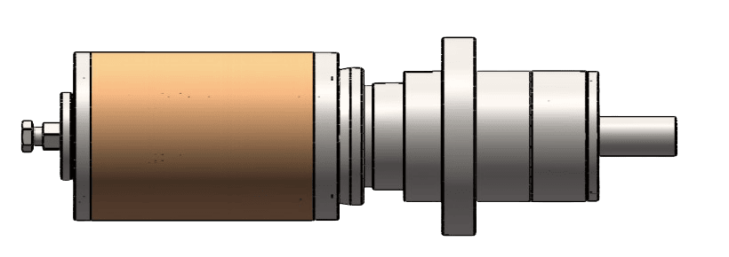
Cantilever spindles
The single-ended spindle arrangement provides access for maintenance. The technical presentation describes service access without removing the complete spindle assembly. Bearing condition, roller grooves and alignment remain part of routine process control.
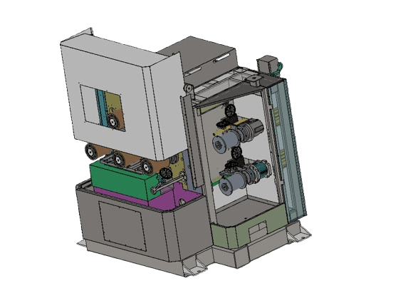
Independent drives and two material positions
Four independent motors drive the rollers. The worktable arrangement carries two material plates for straight cutting. Check both workpiece envelopes and the fixture arrangement before planning simultaneous loads.
Servo control and process protection
The EtherCAT control system coordinates spindle rotation, wire pay-off, take-up, traverse, tension and table feed using servo drives. Process monitoring provides warnings or stops according to alarm severity. Wire-break protection stops the machine after a detected break to reduce the risk of further damage; it does not replace correct setup.
SOM-220D or SOM4-750D?
Select by part geometry first. SOM-220D covers straight slices from smaller blocks; SOM4-750D combines straight cutting with arc-segment machining. A longer capacity alone does not explain that process difference.
| Модель | Workpiece arrangement | Диапазон срезов | Selection reason |
|---|---|---|---|
| SOM-220D | 220 × 220 × 150 mm × 2 | 2–8 mm | Straight magnet slices, smaller blocks |
| SOM4-750D | 750 × 120 × 150 mm × 2 | 1.5–20 mm | Straight slices and arc magnet segments |
For curved parts, supply the inner radius, outer radius, thickness and finishing allowance. If your requirement is outside either model, use the complete multi wire saw model guide. For low-volume laboratory work, compare SOM200 against the actual workpiece and batch requirement.
What should be agreed before production?
Provide the material grade, magnetization state, block dimensions, holding surfaces, target as-cut thickness and finished-part drawing. Agree the inspection method and acceptance criteria, then record the wire, feed and mounting conditions used in the sample cut.
Evaluate accepted output after cutting and inspection. Include preparation, loading, unloading and changeovers rather than treating maximum wire speed as a throughput figure. For downstream equipment, review grinding and lapping with your finishing requirements.
Utilities and installation
Power supply, coolant, compressed air, foundation, lifting access, service clearance and safety requirements are confirmed with your order — please ask us. Overall dimensions describe the machine, not the complete installation area.
Warranty and support
CE certified · 12-month warranty · Response within 12 hours · Free sample cutting.
Send your magnet block and target slice requirements
Share the material grade, dimensions and required result so the machine configuration and trial scope can be reviewed.
Request free sample cutting- Material and magnetization state
- Block and fixture dimensions
- Target thickness and finishing allowance
- Batch size and inspection criteria