ワイヤーソーイング後の総厚みばらつき(TTV)、反り、たわみ
Total thickness variation is different from warp and bow. Learn how support, sampling and wafer condition affect meaningful post-saw inspection.
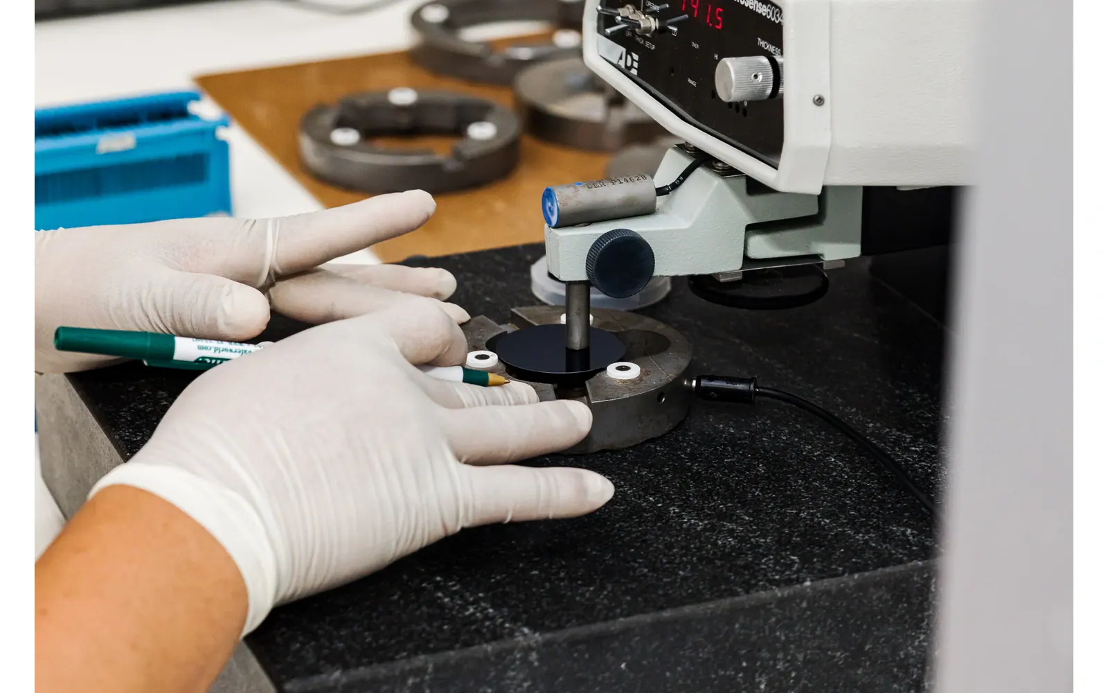
Total thickness variation is not bow, warp or the error of a centre thickness reading. A blank can be uniformly too thin, or meet its average target while one region is too thin to finish. Inspect the thickness range and nominal target separately.
A useful total thickness variation report also states the evaluated area, support and process condition. Without those fields, two laboratories can report different numbers without either one having changed the wafer.
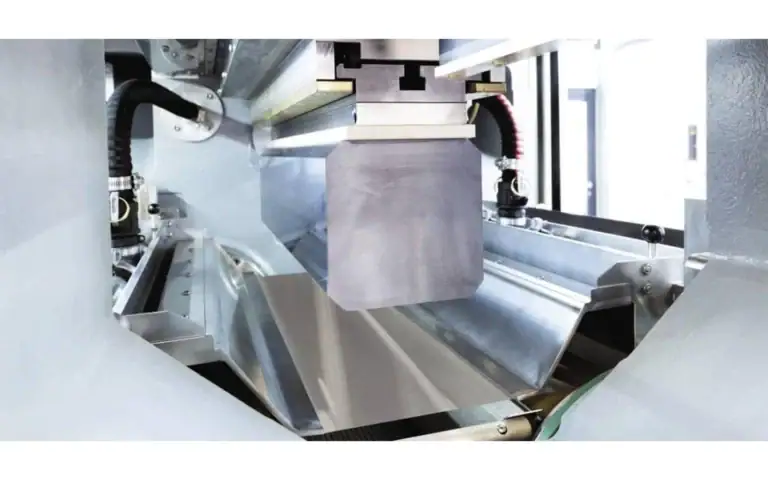
Vimfun SOM200 is a slicing equipment reference, not a metrology specification. A listed thickness tolerance must not be renamed total thickness variation; the inspected area, support and method determine what the measurement establishes.
Define Total Thickness Variation before Comparing Results
A local thickness is the separation between the front and back surfaces at a location, according to the measurement method. TTV is a range across the selected area. It is not the difference between the wafer's average thickness and its nominal target, and it is not the tolerance of a mechanical positioning axis.
NIST research on wafer thickness measurement examines thickness variation using infrared interferometry. Its metrology context illustrates why the measurement method matters. It does not assign a universal TTV limit to every as-cut material or saw.
Can a uniform wafer still be too thin?
Imagine a hypothetical blank whose local thicknesses range from 0.98 to 1.03 mm. Its range is 0.05 mm over the sampled locations. This invented example explains the calculation; it is not a specification or performance result for a Vimfun machine.
That range does not tell you whether the nominal target was 1.00 or 1.10 mm. A blank can be uniformly too thin, or have the correct average thickness but excessive variation. Both target thickness and total thickness variation therefore belong on an acceptance sheet when they matter downstream.
State whether a thickness tolerance applies to a mean, a centre point or all evaluated locations. Without that distinction, the supplier and customer may report different pass/fail conclusions from the same data.
Why are bow and warp different measurements?
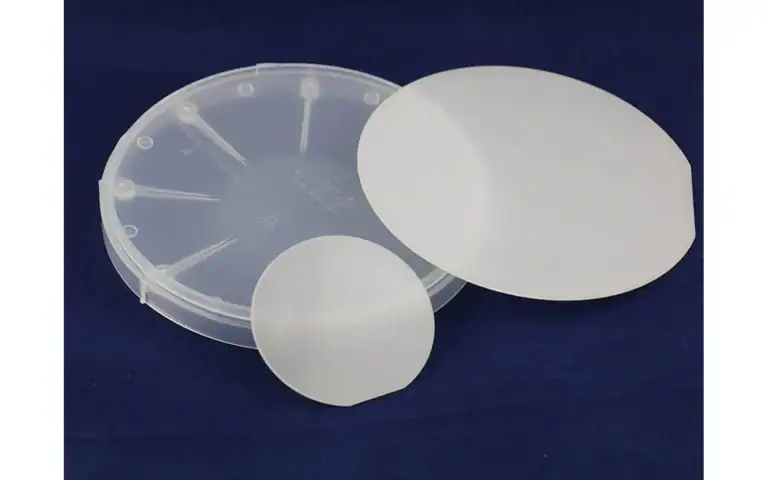
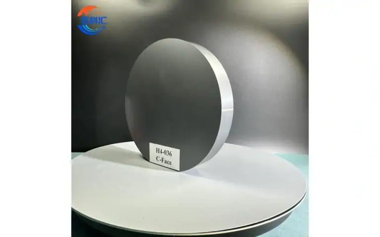
Wafer warp describes shape, whereas thickness variation describes the separation between front and back surfaces. A curved wafer may retain nearly uniform thickness. Conversely, a relatively flat blank can be wedge-shaped. In a TTV silicon wafer inspection, keep the thickness map separate from the shape result; write TTV (total thickness variation) in the report rather than treating all three measurements as one flatness value.
Bow and warp concern deviations of a wafer's median surface from specified reference geometry, with details governed by the measurement convention. They are not simply another name for thickness range. A curved wafer can have relatively uniform thickness, while a wedge-shaped blank can vary in thickness without the same curvature.
To compare total thickness variation with bow or warp, request the definitions used by the inspection system. Identify the support condition and reference plane. A fixture that restrains the wafer can affect shape measurement and should not be omitted from the report.
Do not infer a bow or warp value from a photograph of a wafer resting on a table. The picture can document visible condition, but it lacks the controlled reference and measurement data needed for a quantitative claim.
State the Process Condition of the Sample
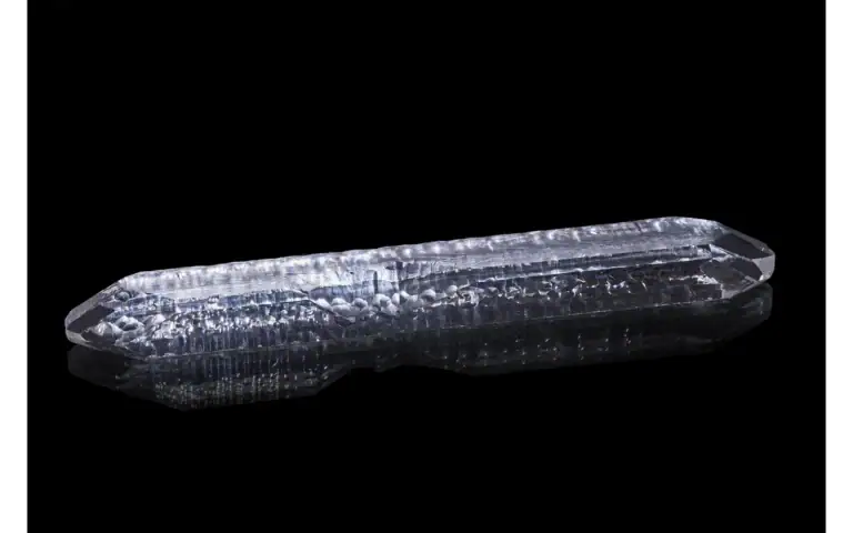
An as-cut blank, a lapped wafer and a polished substrate are different inspection states. Finishing can change thickness and shape, so results should retain their process-stage labels. A published polished-wafer specification cannot automatically be applied to saw output.
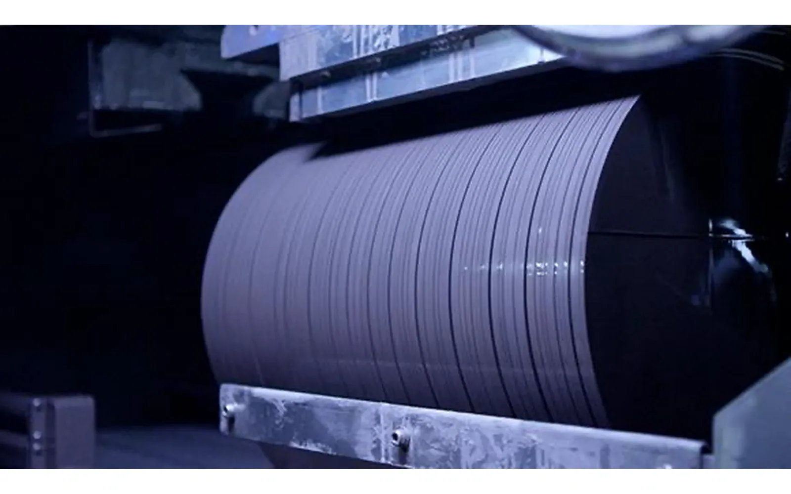
When reviewing シリコンインゴットスライシング, specify which condition is being accepted. If the saw's purpose is to supply blanks for finishing, total thickness variation should be evaluated alongside the available finishing allowance.
Keep surface treatment history with the data. Added films or later thermal processing can change the interpretation of geometry measurements. The receiving operation must know what has happened to the wafer before inspection.
Design the Sampling Pattern
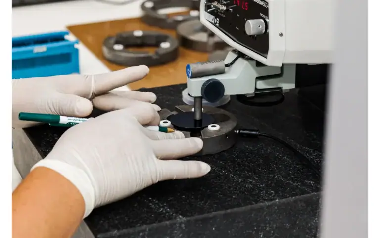
Choose where the thickness is evaluated before the trial. The edge exclusion, number of locations and their distribution affect the ability to detect a wedge or localized variation. A few points may be adequate for a limited screening task but should not be presented as a full surface map.
A total thickness variation comparison needs the same area and sampling method in both runs. Increasing the number of points in one run can reveal extrema that a sparse pattern in the other run misses. Record the actual point locations or retain the map where available.
Also identify instrument capability and calibration status. If the acceptance window is close to the measurement uncertainty, the result needs an agreed decision rule rather than additional decimal places on a spreadsheet.
Retain the location of each thickness sample, not just the minimum and maximum. If an extra measurement point finds a thin spot, the reported range increases even though the wafer has not changed. That is why a sparse centre-and-edge check and a full map should not be compared without identifying their coverage.
For total thickness variation, the illustrative 0.98–1.03 mm range gives 0.05 mm, or 50 µm, across those sampled locations. It says nothing about an unmeasured region. The example is arithmetic, not a measured saw result.
I'd put three fields beside every total thickness variation number: evaluation area, support condition and sample state. “As-cut, defined edge exclusion, named support” is more useful than “high precision.” The pitfall is reporting a polished-wafer result as though it characterized the uncorrected blank.
The map matters.
What happens when the support changes?
Contact and noncontact methods can involve different support arrangements. The fixture must be compatible with the sample thickness and condition. Document whether the wafer is free, supported at defined locations or held by a chuck according to the method.
Total thickness variation data without support information can be difficult to compare, particularly for thin or curved specimens. Repeating a reading under a different holding arrangement may change the result for reasons unrelated to the original cut.
Avoid applying excessive handling force simply to make a reading stable. Follow the instrument and site procedure. If an as-cut surface is unsuitable for a selected method, agree on another method or describe the limitation instead of silently treating uncertain readings as accepted data.
Investigate Trends across the Slice Sequence
Preserve slice order and compare maps or measurements by position. A trend across a batch can point to a setup or process change, but the pattern alone does not identify the cause. Investigate mounting, guide condition, cutting behaviour, release and measurement consistency.
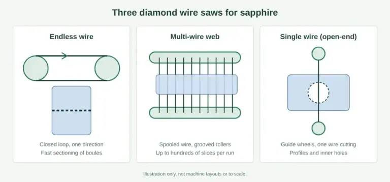
For equipment context, the マルチワイヤーソー overview and 逆マルチワイヤーソー configuration describe different aspects of the setup. Neither link establishes a total thickness variation result for a customer's material.
Record interrupted runs and operator adjustments. Otherwise, samples measured together may actually represent different cutting conditions, making a batch average misleading.
Connect the Result to Finishing
The receiving operation needs enough stock to reach the final geometry without creating an undersized part. A thickness map can help it understand whether the blank offers that allowance across the relevant area. Average thickness alone may hide a locally thin region.
Assess total thickness variation together with edge defects, surface condition and any required damage evaluation. Reducing TTV while leaving insufficient finishing stock does not solve the downstream problem.
If a finishing trial is performed, keep before-and-after measurements linked to the same sample. That shows what the finishing step changed and avoids crediting the saw with a result measured only after correction.
Keep the Measurement Map with the Result
Retain the measured locations, not only the largest and smallest numbers. A result without its map cannot show whether the same part of the surface was evaluated in another run. Record the point identifiers and exclusions so a second engineer can reproduce the inspection boundary.
For total thickness variation, keep nominal thickness in a separate field. A small measured range does not prove that the entire blank lies inside its required thickness window. The receiver needs both the target relationship and the variation information. Combining them under a single label makes a report harder to interpret.
Describe the support condition in terms another operator can reproduce. Record which surfaces contact the support and whether the measurement arrangement differs between as-cut and finished samples. If the support changes during an investigation, keep those results in separate comparison groups until the effect is understood.
State the resolution and relevant measurement limitations from the instrument and method documentation. Do not report more confidence than the setup supports simply because the display shows additional digits. The useful question is whether the inspection can distinguish the differences that matter to acceptance.
A total thickness variation trend across a batch should remain linked to slice order. If an apparent trend is observed, repeat the inspection checks before changing the cutting process. A swapped identifier, changed exclusion region or altered support can produce a misleading comparison even when each individual reading was taken carefully.
Mark missing measurements explicitly. An unmeasured location is not a zero or an interpolated result unless the reporting method specifically defines such treatment. Keep raw observations distinct from any derived display so the receiving team can see the actual evidence.
Before setting an acceptance limit, ask which measurement state it applies to. An as-cut screening limit and a finished-substrate specification may serve different decisions. The report should name that state and its approved criterion rather than treating every thickness map as a final wafer certificate.
| 決定フィールド | 保持する証拠 |
|---|---|
| Area definition | Locations, edge exclusion and missing data |
| Setup definition | Support, instrument and measurement state |
| Batch traceability | Slice position and repeat-inspection record |
質問に答えるページを選択してください
This article answers: Are two reported thickness ranges based on the same measurement definition? It does not replace the following equipment or application scopes.
| あなたの質問 | 関連ページ | 境界 |
|---|---|---|
| シリコンインゴットスライシングのコンテキストが必要ですか? | シリコンインゴットスライシング | 受信タスクのアプリケーションまたはプロセスコンテキスト |
| バッチワイヤーソーイング機器はどのように異なりますか? | マルチワイヤーソー | 受信タスクのアプリケーションまたはプロセスコンテキスト |
| Need the inverted multi wire saw context? | 逆マルチワイヤーソー | 機器構成とその指定された範囲 |
よくあるご質問
Can one reading establish total thickness variation?
No. Total thickness variation describes a range over an evaluated area. A single reading can indicate thickness at that location but cannot establish the range. Use the agreed sampling or mapping method and report its area definition.
Does low total thickness variation prove the blank is thick enough?
No. Check nominal thickness and the local thickness window as well. A uniformly undersized blank can still be unsuitable for finishing. The variation result and the required thickness target answer separate acceptance questions.
Can total thickness variation results use different supports?
Only after establishing that the comparison remains valid under the method being used. Record the changed support and inspection state. Total thickness variation values without those conditions may not describe equivalent measurements, even when the units match.
Report What Was Actually Established
A useful inspection report names the material, sample identity, process condition, measurement method, support, evaluation area and sampling pattern. Include the thickness results and any applicable uncertainty or decision rule. Keep nominal-thickness acceptance, TTV acceptance and shape acceptance separate.
Total thickness variation becomes useful when it describes a reproducible measurement tied to a clear requirement. For a new process, agree on that requirement before cutting and return representative blanks for the receiving team's assessment. The aim is comparable evidence about usable geometry, not a quality adjective attached to one selected sample.
Agree on the thickness target, mapping pattern, edge exclusion and support before cutting. Return the map with slice identity and process state, not only the range. If total thickness variation is excessive, compare the ordered maps and setup history before adjusting the saw; first exclude a changed measurement or holding condition.