Wafer Slicing vs Wafer Dicing: Two Different Saws
Wafer slicing vs dicing separates two manufacturing stages: ingot-to-wafer blanks and wafer-to-dies. Match the saw to the actual input and output.
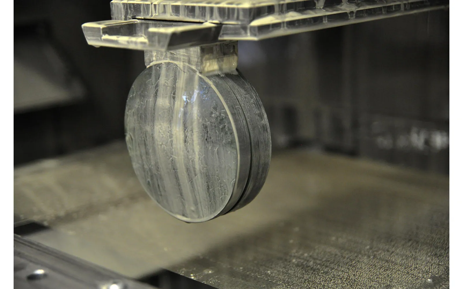
Wafer slicing vs dicing is settled by the input and output: an ingot becomes wafer blanks; a wafer becomes separate dies or pieces according to a layout. Ask for the first when you need substrates, and the second when you need singulation. A shared word such as “saw” does not make the machines interchangeable.
A quick wafer slicing vs dicing check can prevent the wrong enquiry: sketch the material before and after the operation. Thickness generation from bulk stock and lateral separation of a wafer require different support, references and acceptance evidence.
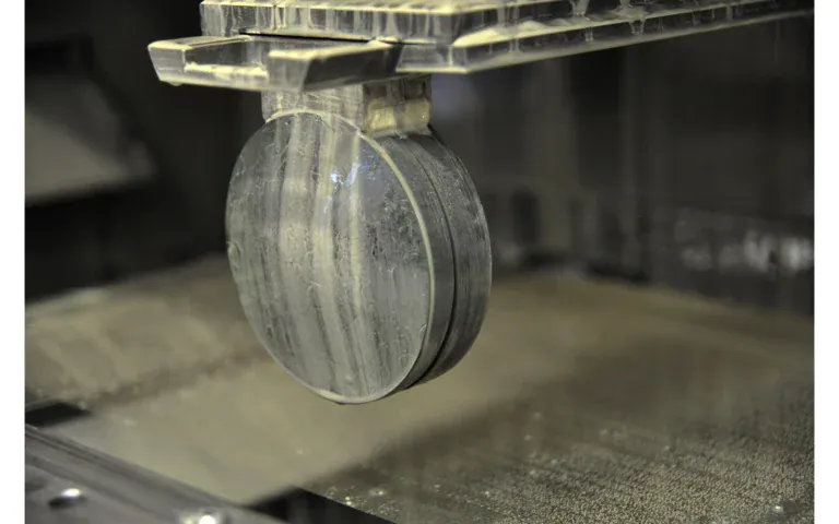
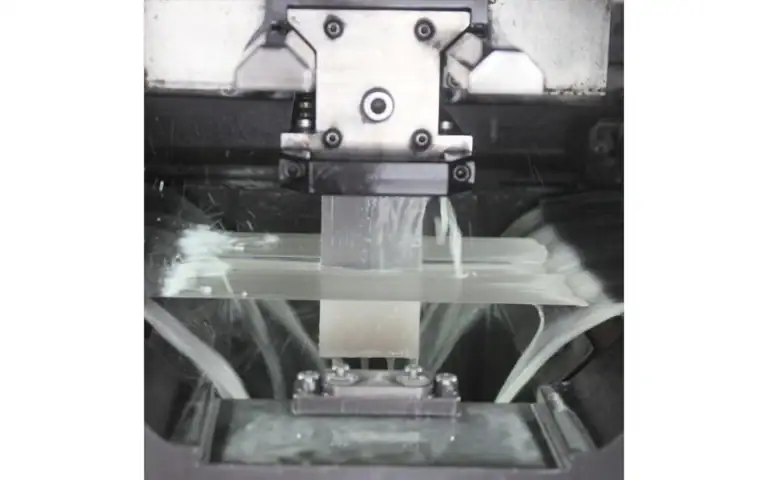
Vimfun SOM200 lists ingot and block slicing applications. In a wafer slicing vs dicing comparison, that is a reference for the blank-making stage, not evidence that it performs device-wafer singulation or follows a die-street layout.
Wafer Slicing vs Dicing: What Enters and Leaves?
Slicing begins with an ingot or another bulk form intended to become substrates. The output is a set of blanks that may still need finishing. Dicing begins with a wafer or processed substrate and follows a separation layout to produce individual pieces.
Die wafer dicing overview describes singulation as a distinct operation. That distinction determines the equipment category before questions about speed or tolerances become meaningful. A drawing of the input and desired output often resolves the terminology immediately.
What material enters the machine?
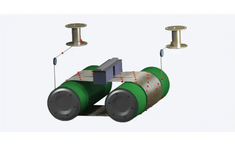
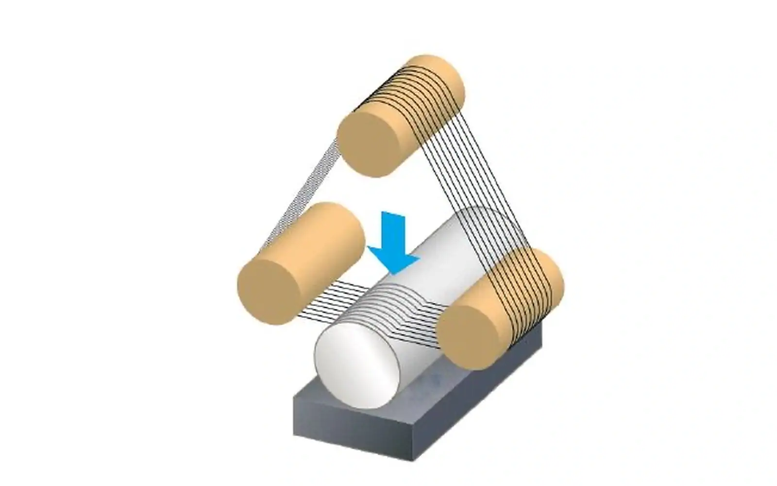
A wafer saw quotation can refer to different operations, so specify the incoming object. The slicing saw vs dicing saw distinction is ingot-to-blank production versus wafer-to-piece separation. A multi-wire slicing arrangement establishes repeated planes through bulk stock; a dicing arrangement follows a lateral layout in an existing wafer. Their fixtures, output counts and receiving requirements differ.
An ingot is bulk stock with a usable length, cross-section and intended slicing plane. A wafer is a plate whose front and back condition, thickness and lateral pattern can matter to separation. A machine suitable for one input is not automatically suitable for the other.
When comparing wafer slicing vs dicing, identify whether the supplied material is unprocessed stock, a finished substrate or a wafer carrying devices or other features. The answer changes what must be protected and which parts of the workpiece can be used for support.
Do not use outside diameter as the only equipment check. The mounted assembly, required motion and separation layout must also fit the proposed process.
Slicing Establishes Blank Thickness
The slicing arrangement defines planes through the bulk material. In a multi-line setup, repeated positions form several blanks within one mounting. The retained thickness depends on the geometry and effective cutting width, while the receiving operation determines the finishing allowance.
For the ingot stage, see Schneiden von Siliziumbarren. The required blank should be defined separately from a polished substrate or finished device.
Wafer slicing vs dicing therefore involves different dimensional targets. Slicing primarily establishes the thickness and condition of a substrate blank; dicing follows the lateral separation layout of a wafer. Both can involve other important geometric requirements, but those main targets should not be confused.
Which layout defines the separated pieces?
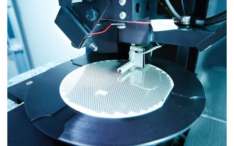
A dicing request should identify the piece layout, permitted cutting regions, wafer condition and requirements for the separated parts. Where devices are present, the separation route must respect the design and approved process. A blank-substrate slicing plan does not provide those details.
In wafer slicing vs dicing discussions, avoid assuming that “smaller pieces” is a complete singulation specification. The supplier needs to know the piece geometry, wafer thickness, relevant front and back features and how the pieces will be handled afterward.
Different dicing technologies may be proposed for different tasks. Naming a blade or laser does not establish suitability by itself; the actual wafer and output condition need a qualified comparison.
Workholding Solves Different Support Problems
An ingot fixture locates bulk material relative to the intended slicing planes and supports blanks as they separate. A wafer-separation fixture must hold a thin substrate and retain or handle individual pieces after the cut. These are different mechanical interfaces.
Wafer slicing vs dicing is therefore also a question of what remains supported near completion. Examine the fixture at the final stage, not only while the initial workpiece is intact. Plan release and transfer before the trial.
The approved attachment and release method must be compatible with the material and receiving process. Do not transfer a bonding system from an ingot trial into a processed-wafer route without the relevant assessment.
Put three items on the request: input form, separation planes and retained product. For an ingot, describe its usable section and required blanks. For a wafer, identify the separation layout and any surface features that must be protected. These descriptions are more useful than the phrase “small cutting machine.”
Wafer slicing vs dicing also changes what must remain held after the cut. The ingot fixture must preserve the slicing reference and support the forming blanks. A wafer-separation arrangement must retain the individual pieces according to its approved route. Copying one attachment method to the other can answer the wrong holding problem.
I'd reject a quotation that reports only an unlabeled “pieces per hour” figure. In wafer slicing vs dicing, pieces can mean blanks, wafers processed or separated dies. Require the input, batch and accepted output condition beside the number before comparing proposals.
Draw the transformation first.
Damage Is Judged against Different Receivers
A sliced blank may proceed to material-removing finishing operations. A diced device or small component may have a different opportunity for correction and different vulnerable features. The acceptance sheet should identify the actual receiver rather than simply demanding “low damage.”
For wafer slicing vs dicing, specify edge defects, surface condition and any internal assessment separately. State what can be measured by the equipment supplier and what belongs to the customer's qualification process.
A clean photograph cannot establish every acceptance feature. Preserve representative rejected pieces and the process history where a failure investigation is needed.
Material Loss Has a Different Layout
In slicing, cutting width repeats between retained blanks along the usable stock. In dicing, material is removed along the defined separation paths in the wafer layout. The useful material balance depends on the actual design and acceptance stage.
Compare wafer slicing vs dicing recovery only after defining the denominator. Ingot-to-blank recovery and accepted die count describe different products. A headline yield from one operation should not be used as a benchmark for the other.
Include rejects, end or edge allowances and any subsequent removal within the stated boundary. Keep calculated geometric output separate from output that passed inspection.
What does the quoted throughput actually count?
Slices per cycle, wafers processed and accepted separated pieces are different measures. A supplier's throughput statement should name the input, batch and output condition. Cutting time also needs to be distinguished from setup, release, cleaning and inspection.
For an ingot-to-blank project, review a Waffenschneidemaschine using representative stock and a blank acceptance plan. This link concerns the slicing stage; it does not claim that the same equipment performs device singulation.
When comparing wafer slicing vs dicing quotations, check that each proposal answers the requested operation. A technically impressive quotation for the wrong stage is still unsuitable.
Prepare the Enquiry with Input and Output Drawings
Send material identification, input dimensions and a drawing of the required output. For an ingot, include the desired plane, blank thickness, finishing allowance and useful stock. For a wafer, include the separation layout, thickness, relevant surface condition and retention requirements.
Name the acceptance method and the operation that receives the pieces. State whether the sample represents production stock or a selected demonstration specimen. Ask for measurements corresponding to the required stage rather than a generic quality description.
A wafer slicing vs dicing trial should resolve an operation-specific uncertainty. For slicing, that might be usable blank geometry; for dicing, it might be the separation boundary and retained-piece condition. Keep those conclusions within their tested scope.
Draw the Input and Output on the Same Enquiry
Put the incoming object and the required separated object on one drawing. If the input is an ingot and the output is a set of blanks, the enquiry concerns the blank-making route. If the input is a wafer carrying a separation layout, the enquiry concerns that layout and its receiver. The word saw does not resolve this difference.
For wafer slicing vs dicing, keep throughput units attached to the product. A count of wafer blanks and a count of separated pieces can differ in meaning even when both are reported per cycle. Ask what enters the count, when acceptance occurs and which handling steps are included before comparing capacity statements.
Reference transfer also belongs to the correct stage. An ingot-to-blank request needs the material plane and locating relationship. A wafer-to-piece request needs the defined layout and the references that locate it. A drawing useful at one stage may not give the other operator the information needed to perform the task.
Do not transfer a support claim across these stages without review. Describe the actual incoming assembly, the parts that remain supported after each separation and the receiving package. The fixture question follows the product and cut layout, not the fact that both operations involve brittle material.
The wafer slicing vs dicing inspection boundary should be equally clear. Name which dimensions and defects are assessed at each stage and which qualifications belong downstream. A supplier demonstrating blank dimensions is not necessarily demonstrating the requirements of singulated pieces.
Use the distinction when routing an enquiry. Ask the equipment supplier to confirm its operation scope from the drawing, and retain that confirmation with the proposal. This prevents an equipment name from being treated as a capability that the underlying configuration does not describe.
If both operations belong to the full manufacturing route, show them as separate stations with separate receiving requirements. The connection between them includes intermediate processing and inspection, not just a transfer of pieces from one saw to another. That is the practical value of distinguishing the stages before equipment selection.
| Entscheidungsfeld | Zu behaltende Beweise |
|---|---|
| Incoming object | Ingot/block or wafer with a separation layout |
| Output object | Blank or individually separated piece |
| Acceptance boundary | Receiving condition and operations included |
Wählen Sie die Seite, die Ihre Frage beantwortet
This article answers: Is the task ingot-to-blank separation or wafer-to-piece singulation? It does not replace the following equipment or application scopes.
| Ihre Frage | Relevante Seite | Grenze |
|---|---|---|
| Benötigen Sie den Kontext des Silizium-Ingot-Schneidens? | Schneiden von Siliziumbarren | Anwendungs- oder Prozesskontext für die empfangende Aufgabe |
| Benötigen Sie den Kontext der Wafer-Schneidemaschine? | Waffenschneidemaschine | Anwendungs- oder Prozesskontext für die empfangende Aufgabe |
FAQ
What is the defining wafer slicing vs dicing distinction?
Wafer slicing vs dicing distinguishes blank creation from later separation according to a wafer layout. Define the incoming and outgoing objects first. Shared terminology such as cutting or sawing does not make the equipment duties equivalent.
Can a wafer slicing vs dicing comparison reuse blank capacity?
Not without a documented configuration and task that actually establish that duty. Keep the counted product and cycle boundary explicit. A blank-making result does not qualify a different cut layout or downstream output.
Which drawing resolves a wafer slicing vs dicing enquiry?
Send input and output drawings together and identify the receiving condition. Ask the supplier which operation its proposal covers. This usually resolves the stage question more effectively than a longer list of ambiguous machine names.
Use the Distinction to Select the Next Step
The simplest procurement check is to describe the physical transformation. If bulk stock becomes wafer blanks, the project is at the slicing stage. If a wafer becomes individual pieces according to a layout, the project is at the dicing stage.
Send before-and-after drawings with material identity and the accepted output condition. If the job is ingot-to-blank, specify plane, thickness and finishing allowance. If it is wafer-to-piece, specify layout and retention. Use those fields to classify wafer slicing vs dicing, then request an operation-specific trial and a clearly labeled throughput boundary.