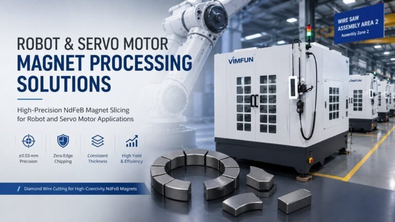
Los motores eléctricos consumen más imanes permanentes que cualquier otra aplicación. Desde servomotores industriales hasta electrodomésticos, desde motores de herramientas eléctricas hasta compresores de climatización, cada motor de CC sin escobillas o motor síncrono de imanes permanentes contiene segmentos de imán de NdFeB o SmCo cortados con precisión. El equipo de corte de imanes para motores utilizado para producir estos segmentos determina la precisión dimensional, la utilización del material y el rendimiento de la producción.
Esta guía cubre lo que el equipo de corte de imanes para motores necesita hacer, cómo seleccionarlo y configurarlo para diferentes geometrías de imanes para motores, y cómo optimizar los parámetros de corte para los grados de NdFeB comúnmente utilizados en aplicaciones de motores.

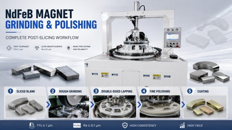
¿Qué es el equipo de corte de imanes para motores?
El equipo de corte de imanes para motores es maquinaria de corte de precisión diseñada para cortar bloques de imanes de NdFeB o SmCo sinterizados en segmentos delgados utilizados en rotores y estatores de motores eléctricos. A diferencia de las máquinas de corte de propósito general, el equipo de corte de imanes para motores debe manejar la combinación específica de desafíos que presentan los materiales de imanes permanentes:
- Dureza y fragilidad extremas. El NdFeB sinterizado tiene una dureza Vickers de 550–650 HV y prácticamente cero ductilidad. Las fuerzas de corte que serían triviales en metales causan astillado y fractura en los materiales magnéticos.
- Sensibilidad a la corrosión. Los imanes de NdFeB se corroen rápidamente cuando se exponen a refrigerantes a base de agua sin la protección adecuada de la superficie. El proceso de corte debe utilizar una química de refrigerante apropiada o técnicas de corte en seco con extracción de polvo eficaz.
- Requisitos dimensionales estrictos. Los segmentos de imanes para motores suelen requerir tolerancias de espesor de ±0.05 mm y paralelismo dentro de 0.02 mm. Estas tolerancias afectan directamente la uniformidad del entrehierro del motor y el rendimiento electromagnético.
- Alto costo del material. El NdFeB sinterizado con propiedades de grado de motor (N42–N52, o grados de alta temperatura como N38SH–N48SH) cuesta entre 80 y 150 USD por kilogramo, dependiendo del grado y las condiciones del mercado. Cada milímetro de desperdicio de corte es dinero perdido.
Equipo de corte de imanes para motores — Especificaciones clave
| Parámetro | Sierra de hilo diamantado | Sierra multihilo | Sierra de ID (diámetro interior) |
|---|---|---|---|
| Ancho del corte | 0.30–0.40 mm | 0.30–0.40 mm | 0.8–1.5 mm |
| Precisión de corte (TTV) | ±0.03 mm | ±0.03 mm | ±0.05 mm |
| Rugosidad superficial (Ra) | 0.8–1.5 μm | 0.8–1.5 μm | 1.0–2.5 μm |
| Rendimiento (cortes/hora) | 10–30 (alambre simple) | 100–500 (alambre múltiple) | 20–60 |
| Tamaño máximo del bloque | Dependiente del modelo | Hasta 200 mm de longitud | Limitado por el ID de la cuchilla |
| Ideal para | Prototipos, segmentos de arco | Producción de alto volumen | Cortes gruesos, bloques grandes |
Para operaciones que producen más de 5,000 segmentos de imanes de motor al mes, sierras multihilo ofrezca la mejor combinación de rendimiento y eficiencia de material. Las sierras de alambre de diamante de alambre simple se adaptan mejor a cantidades de prototipos o cortes de contorno complejos en imanes de motor en forma de arco.
Cómo la geometría del imán del motor afecta la selección del equipo
No todos los imanes de motor tienen la misma forma. La topología del motor determina la geometría del imán, lo que a su vez determina el equipo de corte de imanes de motor que necesita.
Segmentos rectangulares/bloques (motores IPM)
Motores de imán permanente interior (IPM): el diseño dominante en servomotores industriales, compresores HVAC y muchos motores de electrodomésticos, utilizan segmentos de imán rectangulares o trapezoidales insertados en ranuras en el apilamiento de laminaciones del rotor.
Dimensiones típicas: 20–80 mm de longitud × 10–30 mm de ancho × 2–6 mm de grosor
Requisito del equipo: Las sierras multihilo son ideales para segmentos rectangulares. El bloque de imán se monta y se corta en múltiples segmentos simultáneamente, con el espaciado de los hilos que determina el grosor del segmento. Un solo ciclo de corte puede producir 20–100+ segmentos de un bloque.
Segmentos de arco (motores SPM)
Los motores de imán permanente de superficie (SPM) utilizan segmentos de imán curvos (en forma de arco) unidos directamente a la superficie del rotor. Estos son comunes en motores más pequeños para herramientas eléctricas, motores de drones y algunas aplicaciones industriales.
Dimensiones típicas: Radio del arco 15–60 mm, grosor 2–5 mm, ángulo del arco 30°–120°
Requisito del equipo: Los segmentos de arco requieren capacidad de corte de contorno. Sierras de hilo de diamante de un solo hilo con control de trayectoria CNC, o dedicadas máquinas de rectificado de imanes de arco para el conformado final después del corte aproximado. Las sierras multihilo no pueden producir geometrías de arco directamente.
Pan de molde / Arco segmentado (motores de radio/tipo V)
Los motores IPM de tipo radio y de disposición en V utilizan segmentos en forma de cuña o de pan de molde. Estos diseños están ganando popularidad en motores industriales de alta eficiencia y algunas aplicaciones de vehículos eléctricos.
Dimensiones típicas: Sección transversal variable, grosor de 3–8 mm en el punto más delgado
Requisito del equipo: Sierras de hilo multieje que pueden inclinar el corte, o corte aproximado con una sierra multihilo estándar seguido de rectificado a la geometría final. El corte aproximado utiliza equipo de corte de imanes de motor; el corte de acabado utiliza equipo de rectificado.
Parámetros de corte para imanes de NdFeB de grado de motor
Las aplicaciones de motores utilizan principalmente NdFeB sinterizado en grados N35–N52 (estándar) o N33SH–N48SH (alta temperatura). Estos grados comparten características de corte similares pero difieren en dureza y fragilidad a medida que aumenta el (BH)max.
Parámetros recomendados de sierra de hilo para imanes de motor NdFeB
| Parámetro | Grados estándar (N35–N48) | Grados de alta temperatura (N33SH–N48SH) |
|---|---|---|
| Diámetro del cable | 0.30–0.35 mm | 0.30–0.35 mm |
| Velocidad del cable | 8–15 m/s | 6–12 m/s (más lento) |
| Velocidad de avance | 15–30 mm/min | 10–25 mm/min (más lento) |
| Refrigerante | A base de agua con inhibidor de corrosión | A base de agua con inhibidor de corrosión |
| Tensión del hilo | 25–35 N | 25–35 N |
| Ra esperada | 0.8–1.5 μm | 1.0–2.0 μm |
Nota crítica sobre el refrigerante: Los imanes de NdFeB se corroen en agua pura en cuestión de horas. Utilice siempre refrigerante con inhibidores de óxido formulados específicamente para imanes de tierras raras. Después del corte, seque los segmentos inmediatamente y aplique protección temporal contra la corrosión (recubrimiento de aceite o envasado al vacío) antes de que pasen a rectificado o recubrimiento.
Cálculo de rendimiento de sierra multihilo
Para segmentos de imanes de motor rectangulares, el rendimiento de la sierra multihilo depende de:
- Longitud del bloque (determina cuántos hilos entran en contacto con el material simultáneamente)
- Velocidad de avance (limitado por la dureza del material y el descascarillado aceptable)
- Paso del hilo (espesor del segmento + ancho de corte)
Ejemplo: Un bloque de NdFeB de 150 mm cortado en segmentos de 3 mm con un corte de 0.35 mm:
- Cortes por bloque: 150 ÷ (3.0 + 0.35) ≈ 44 segmentos
- Tiempo de corte a una velocidad de avance de 20 mm/min a través de un bloque de 25 mm de ancho: ~1.5 minutos
- Rendimiento: aproximadamente 44 segmentos por ciclo de 1.5 minutos — muy superior a lo que pueden lograr las sierras de hilo único o de ID.
Es por eso que sierras multihilo dominan la producción de imanes de motor de alto volumen.
Solución de problemas de equipos de corte de imanes de motor
Descascarillado en los bordes de corte: ¿Cómo reducirlo?
El astillado del borde es el defecto más común en el corte de imanes de motor. Las astillas mayores de 0,3 mm suelen hacer que el segmento falle la inspección dimensional, y las astillas sueltas pueden contaminar el ensamblaje del motor.
Causas raíz y soluciones:
- Velocidad de avance demasiado alta — Reduzca la velocidad de avance entre un 15 y un 20 % y reevalúe la calidad del borde. El NdFeB no tiene ductilidad, por lo que incluso una pequeña fuerza excesiva provoca fracturas frágiles en el borde de corte.
- Alambre desgastado o dañado — Compruebe el estado del recubrimiento de diamante. El alambre con el núcleo expuesto roza contra el imán y provoca fracturas por desprendimiento en lugar de cortes limpios.
- Sin soporte de salida — El alambre atraviesa material sin soporte en el lado de salida, lo que provoca astillas por soplado. Utilice un bloque de soporte sacrificial (grafito o cerámica blanda) sujeto contra la cara de salida.
- Vibración — Compruebe la tensión del alambre y la rigidez del bastidor de la máquina. Cualquier vibración del alambre se traduce directamente en superficies de corte irregulares y daños en los bordes de materiales frágiles.
Variación de espesor en el lote — ¿Qué la causa?
Si los segmentos de imán de motor del mismo lote de corte presentan una variación de espesor superior a ±0,05 mm, el problema suele ser mecánico y no paramétrico:
- Deflexión del alambre durante el corte — Aumente la tensión del alambre (dentro de los límites del fabricante) o reduzca la velocidad de avance para disminuir la fuerza de corte.
- Desalineación del montaje del bloque — Verifique que el bloque de imán esté asentado plano y escuadrado contra las superficies de referencia de montaje.
- Deriva térmica — Los ciclos de corte largos generan calor. Si la máquina carece de compensación térmica, las dimensiones se desvían a medida que los componentes se expanden. Verifique y recalibre cada 30 minutos de corte continuo.
Corrosión que aparece antes del recubrimiento: ¿cómo prevenirla?
Si los segmentos de NdFeB muestran manchas de óxido entre el corte y la etapa de recubrimiento, el lapso del proceso es demasiado largo o la protección intermedia es inadecuada.
Soluciones inmediatas:
- Seque los segmentos con aire comprimido inmediatamente después del corte.
- Aplique una fina capa de aceite antioxidante dentro de los 30 minutos posteriores al corte.
- Almacene los segmentos cortados en bolsas selladas al vacío con desecante si el paso de recubrimiento está a más de 24 horas de distancia.
- Nunca deje los segmentos de NdFeB húmedos expuestos al aire ambiente; la corrosión comienza en 2 a 4 horas en ambientes húmedos.
Según Arnold Magnetic Technologies, el manejo adecuado del NdFeB sinterizado entre los pasos de procesamiento es fundamental para mantener las propiedades magnéticas y mecánicas.
Equipo de corte de imanes para motores vs. Equipo para imanes de motores de vehículos eléctricos: ¿Qué es diferente?
Ambos términos describen equipos de corte para imanes de motores, pero se dirigen a diferentes segmentos del mercado:
| Factor | Equipo de corte de imanes para motores (Esta página) | Equipo de fabricación de imanes para motores de vehículos eléctricos |
|---|---|---|
| Alcance de la aplicación | Todos los tipos de motores eléctricos (industriales, electrodomésticos, herramientas eléctricas, HVAC, etc.) | Específicamente motores de tracción para vehículos eléctricos |
| Volumen típico | 1.000–100.000 piezas/mes | 100.000–1.000.000+ piezas/mes |
| Forma dominante del imán | Mixta (rectangular, de arco, en cuña) | Segmentos de arco y forma de pan de molde para rotores IPM/SPM |
| Clase de tolerancia | ±0,05 mm estándar | ±0,03–0,05 mm (más estricta para automoción) |
| Sistema de calidad | ISO 9001 | IATF 16949 (calidad automotriz) |
| Trazabilidad | Nivel de lote | Nivel de pieza (requisito del OEM de automoción) |
La tecnología de corte es fundamentalmente la misma — sierras de hilo de diamante y sierras multihilo —, pero la producción de imanes para motores de VE añade requisitos específicos de la industria automotriz en torno a la trazabilidad, el control estadístico de procesos y la documentación PPAP que la producción de imanes para motores industriales en general no requiere.
Cómo seleccionar equipos de corte de imanes para motores para su producción
La elección del equipo de corte de imanes para motores adecuado se reduce a tres factores:
1. El volumen determina el tipo de máquina.
- Menos de 5.000 segmentos/mes → Sierra de hilo de diamante de hilo único (flexible, menor coste de capital)
- 5.000–50.000 segmentos/mes → Sierra multihilo (alto rendimiento, bajo desperdicio de corte)
- Más de 50.000 segmentos/mes → Múltiples sierras multihilo con carga automatizada
2. La geometría determina el método de corte.
- Segmentos rectangulares → Sierra multihilo (cortes rectos)
- Segmentos de arco → Sierra CNC de hilo único (cortes de contorno) + máquina de rectificado de arco (acabado)
- Formas de cuña/complejas → Sierra de hilo multieje o corte aproximado + rectificado
3. El grado del material determina los parámetros.
- Estándar NdFeB (N35–N48) → Velocidades de avance estándar, refrigerante a base de agua
- NdFeB de alta temperatura (grados SH/UH/EH) → Velocidades de avance 15–20% más lentas, gestión más cuidadosa del refrigerante
- Imanes SmCo → Características de corte completamente diferentes (más duros, menos quebradizos que el NdFeB, mayor tolerancia a la temperatura)
Para obtener orientación sobre el corte imanes de tierras raras en diferentes tipos de materiales, o para recomendaciones específicas Máquina de corte NdFeB basadas en sus requisitos de producción, póngase en contacto con nuestro equipo de ingeniería con las dimensiones de su imán, grado, volumen mensual y especificaciones de tolerancia.