Silicon Nitride Ceramic Cutting Methods
Silicon nitride machining needs a grade-specific cutting and finishing plan. Compare wire, blade and grinding roles and define damage inspection.
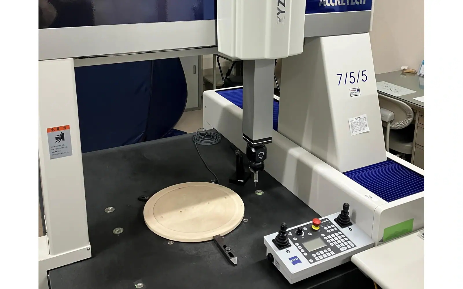
Silicon nitride machining should distinguish separating a plate from finishing its functional surfaces. For repeated plates, assess the wire route; for an individual separation, assess the blade arrangement. Grinding belongs in the route when it must establish a final surface or dimension.
The grade and required flaw assessment control that choice. Silicon nitride machining is not qualified by a smooth photograph: a route that meets dimensions can still leave a defect relevant to the finished component.
Vimfun SOM4-630D is an equipment reference in the approved silicon nitride machining plan. Its specification names SiC and other advanced ceramics, not a qualified Si3N4 result; confirm the actual grade before treating the machine as a suitable route.
Start Silicon Nitride Machining with the Grade
Silicon nitride ceramics can differ in composition and manufacturing history. Obtain the supplier's material identification and incoming condition. Do not treat a generic chemical formula as a complete description of the stock or infer its behaviour from appearance.
Le NIST ceramics database illustrates the need to associate properties with a particular evaluated material. A property from that resource should not be converted into an untested feed setting or tolerance for your component.
Which features must this operation produce?
A block divided into repeated plates presents a different task from a slot, an individual cutoff or a ground reference surface. The drawing should identify the features to be created and the order in which they are needed.
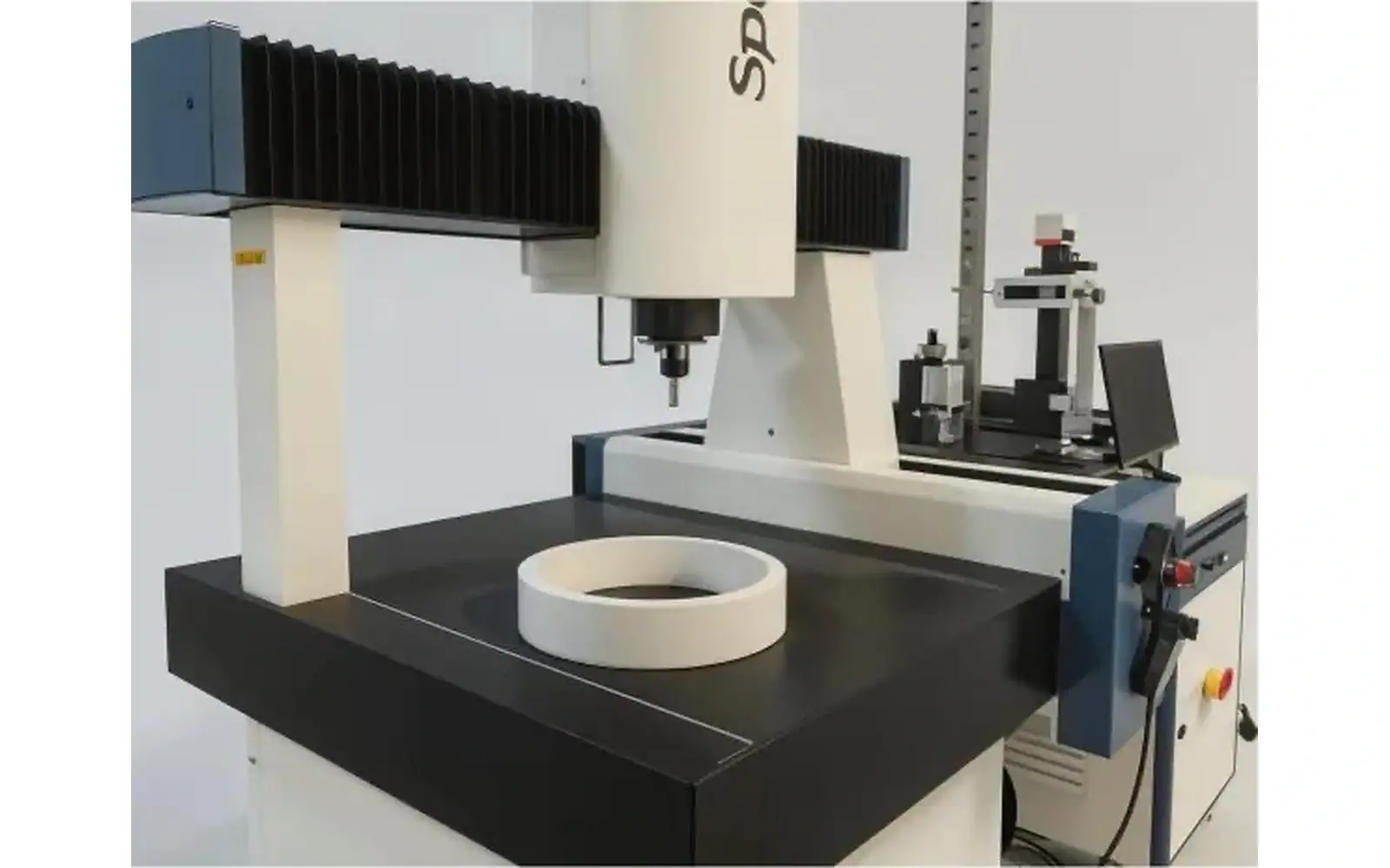
For silicon nitride machining, establish the reference faces and permitted allowances. If slicing supplies blanks for later grinding, describe the blank rather than asking the saw to guarantee the complete final component. The receiving process determines the useful handoff condition.
Le coupe de céramique technique application page focuses on block-to-plate production. Use that boundary when evaluating repeated slices, and state separately any other component features required afterward.
Wire Sawing for Parallel Blanks
The method comparison starts with the requested feature. Wire sawing addresses repeated parallel blanks; a diamond blade addresses a defined separation; grinding establishes or corrects surfaces and geometry. These methods can be consecutive operations rather than substitutes. For a silicon nitride grade, equipment eligibility still requires a representative material trial; a broad ceramic catalogue entry does not establish qualified compatibility.
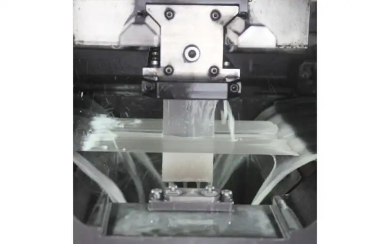
A wire arrangement removes material along a guided path; a multi-line web creates repeated separation planes within a setup. This can be assessed where the objective is a series of plates rather than unrelated localized features.
Silicon nitride machining with a wire system still depends on fixture support, tool condition and the selected output requirement. Narrow cutting width is one potential consideration, but accepted recovery also includes damaged blanks and the material removed later.
Le scie multi-fils à 4 axes provides equipment context for a project assessment. A specific grade, thickness and workpiece configuration require representative evaluation; a model name does not establish their acceptance result.
Blade Cutting for Defined Separations
A blade system can be assessed for individual straight separations where the stock and fixture allow appropriate access. Select the tool and cutting arrangement according to the actual material and machine procedure. Do not assume that a rigid blade eliminates edge or internal damage.
In silicon nitride machining, compare the blade output with the same blank requirement used for another method. Include effective cutting width, edge condition and finishing allowance. A thicker demonstration coupon does not establish the same result at a thin production target.
Consider the number of individual cuts and repeated setups required. Their contribution to process effort can differ from a multi-line batch, even when the final outside dimensions are similar.
Grinding Has a Different Role
Grinding can generate or correct surfaces and dimensions, but its purpose should be stated within the route. It is not simply another word for slicing. A part may need both separation and finishing rather than a choice of only one operation.
For silicon nitride machining, define which surfaces are finished by grinding and how much material is available for removal. Retain the datum relationship between the as-cut blank and the intended final geometry.
A ground surface can still contain machining-related flaws. The relevant question is whether the selected route achieves the accepted component condition, using an appropriate inspection method. Surface appearance alone is not enough to settle that question.
What does a smooth surface leave unverified?
NIST's case study of machining cracks in silicon nitride investigates flaws associated with ground ceramics. It supports the need for appropriate fracture examination; it does not establish a universal damage depth for wire-sawn blanks.
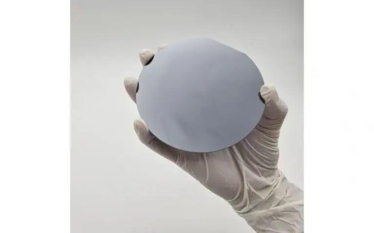
Silicon nitride machining reports should distinguish edge chipping, surface texture, visible cracks and subsurface assessment. State which features were actually examined. A smooth photograph cannot be used to claim that every internal defect was excluded.
If damage is a critical acceptance issue, involve the receiving team's inspection expertise before the trial. Select representative specimens and retain failed pieces so that the cause can be investigated rather than guessed.
The NIST case study concerns machining cracks in ground silicon nitride. It should not be quoted as a measured wire-saw damage depth. Its practical lesson is to retain the failed specimen and enough process context for a relevant fracture investigation.
The SOM4-630D specification lists “cutting accuracy” as ±0.015 mm. That label is not automatically slice-thickness tolerance, TTV or a silicon-nitride-specific result. The listed configuration range does not establish a silicon-nitride-specific operating window, so no range is prescribed for this grade here. Those distinctions matter in silicon nitride machining procurement.
I'd put geometry, visible edges and the required flaw assessment on separate lines of the acceptance sheet. The trap is using one successful dimensional reading to accept all three. For silicon nitride machining, the material grade and component's inspection requirements still determine what evidence is sufficient.
A smooth surface is not a flaw assessment.
Design the Fixture for Entry and Release
The support arrangement changes as stock is divided. Check how the workpiece is located, how cutting access is maintained and how separated blanks remain supported. Avoid judging the fixture only by its apparent rigidity before machining.
Silicon nitride machining should include a planned release and transfer method. If bonding is used, its compatibility and detachment procedure belong in the approved process documentation. The cutting trial should not end at an improvised debonding step.
Photograph the assembly and record accessible defects before and after release. This helps distinguish a cutting problem from damage introduced while detaching, cleaning or packing the blanks.
Does the narrower cut improve accepted recovery?
A material balance includes stock retained in acceptable blanks, effective cutting loss, end allowances, rejects and finishing removal. State the denominator used for recovery: mass, volume or accepted piece count. Keep geometric predictions separate from measured results.
A silicon nitride machining change may improve one part of the route while increasing another. A narrow cut that leaves insufficient finishing stock is not a useful yield improvement. Likewise, additional blank stock may improve finishing success while increasing material use.
Record consumable condition, interrupted runs and setup effort alongside accepted output. This makes the comparison relevant to repeated production rather than only a selected test piece.
Build a Grade-Specific Acceptance Matrix
Start the comparison with the functional geometry and the supplied material identity. A plate blank, an individual cutoff and a final contact surface are different outputs. List them separately so the proposed route shows which operation establishes each feature instead of suggesting that one tool does everything.
For silicon nitride machining, keep a general ceramic capability statement separate from material-specific evidence. A document that mentions advanced ceramics can justify an enquiry, but it does not establish the result for the exact grade in the trial. Ask for the relevant qualification boundary rather than quietly extending the wording.
Put the required defect assessment beside the dimensional requirement. State which visible observations are screening checks and which further evaluation the receiver requires. A surface can appear uniform without answering every flaw question. Do not change an observation into a strength or damage-depth claim that the trial did not measure.
The fixture review should include the completed separation. Identify how the pieces remain supported at entry, exit and release, and how the references stay attached to the batch identity. A fixture that looks rigid while the block is intact may still need a different handling plan once pieces are separated.
A silicon nitride machining comparison should report the output state after each operation. If grinding changes the geometry or surface, retain the earlier measurement instead of overwriting it. This allows the receiver to determine which stage achieved the requirement and which stage introduced an unresolved observation.
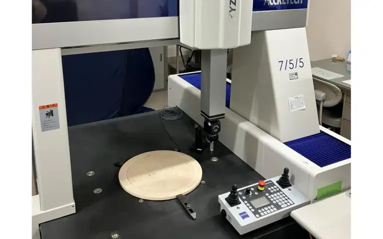
Do not translate the machine’s cutting-accuracy label into a material-specific thickness or TTV guarantee. Use the manufacturer’s term for the configuration reference, then specify the blank’s own acceptance method. Those two statements can coexist without being numerically interchangeable.
For the next enquiry, request a trial that returns both useful pieces and the evidence needed to interpret them. A narrower cut or a faster cycle is not the decision boundary if the functional surface remains unqualified. Choose the route that can demonstrate the required handoff for the actual part.
| Champ de décision | Preuves à conserver |
|---|---|
| Grade evidence | Material identity and relevant compatibility scope |
| Geometry evidence | Operation establishing each required feature |
| Quality evidence | Inspection method, processing state and limitations |
Choisissez la page qui répond à votre question
This article answers: Which operations and inspections are needed for this grade and geometry? It does not replace the following equipment or application scopes.
| Votre question | Page pertinente | Limite |
|---|---|---|
| Besoin du contexte de coupe de céramique d'alumine ? | coupe de céramique technique | Contexte d'application ou de processus pour la tâche de réception |
| Need the 4 axis multi wire saw context? | scie multi-fils à 4 axes | Configuration de l'équipement et sa portée déclarée |
FAQ
Does a general ceramic statement qualify silicon nitride machining?
No. Silicon nitride machining needs evidence for the actual grade and task. Keep the generic capability statement as a basis for enquiry, and ask the supplier to confirm the qualification scope rather than assuming every ceramic is covered.
Are grinding and slicing interchangeable in silicon nitride machining?
They serve different geometric tasks in the route. Identify what each operation must deliver and how the receiving process inspects it. A blank separation and a final functional surface should not share one unexplained acceptance label.
Does machine accuracy establish silicon nitride machining TTV?
Not automatically. Preserve the specification’s terminology and define the output measurement separately. The SOM4-630D reference does not establish a silicon-nitride-specific TTV result simply because an accuracy value is listed.
Prepare a Focused Trial Request
Provide grade identification, incoming dimensions, desired blank drawing, required thickness, reference surfaces and finishing allowance. Identify the defects that would cause rejection and who will measure them. State whether the stock represents the future production grade.
For silicon nitride machining, choose a trial objective that can be answered with the available sample. A small specimen can help assess material separation or release, while larger production geometry may require a later test. Preserve that boundary in the report.
Send the silicon nitride grade and blank drawing, then identify which surfaces will be finished later. Agree on geometry, edge and flaw inspection separately. Do not treat the SOM4-630D accuracy label as a material-specific thickness promise. Compare silicon nitride machining routes with representative blanks and retained rejected specimens, not only successful photographs.