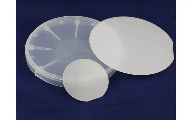
Solar vs Semiconductor Silicon Wafers: How Slicing Requirements Differ
Solar wafer slicing and semiconductor substrates need different acceptance plans. Compare geometry, handling, yield and the receiving process.

Solar wafer slicing and semiconductor-substrate slicing can share a wire mechanism while requiring different blanks. The mistake is comparing slices per cycle before defining the receiving process. A thin photovoltaic blank and a blank reserved for polishing do not have the same material allowance or acceptance boundary.
A PV wafer is a substrate for a photovoltaic product; a semiconductor device wafer serves a different product route. Compare the supplied crystal form, retained shape, blank target, handling requirements and receiving inspection. Both routes can use silicon, but that shared material does not make their slicing requirements interchangeable.
Compare solar wafer slicing using accepted output after the agreed release and inspection steps. Keep material grade, stock shape, thickness and downstream removal visible; otherwise a throughput figure can describe a different product from the one you need.
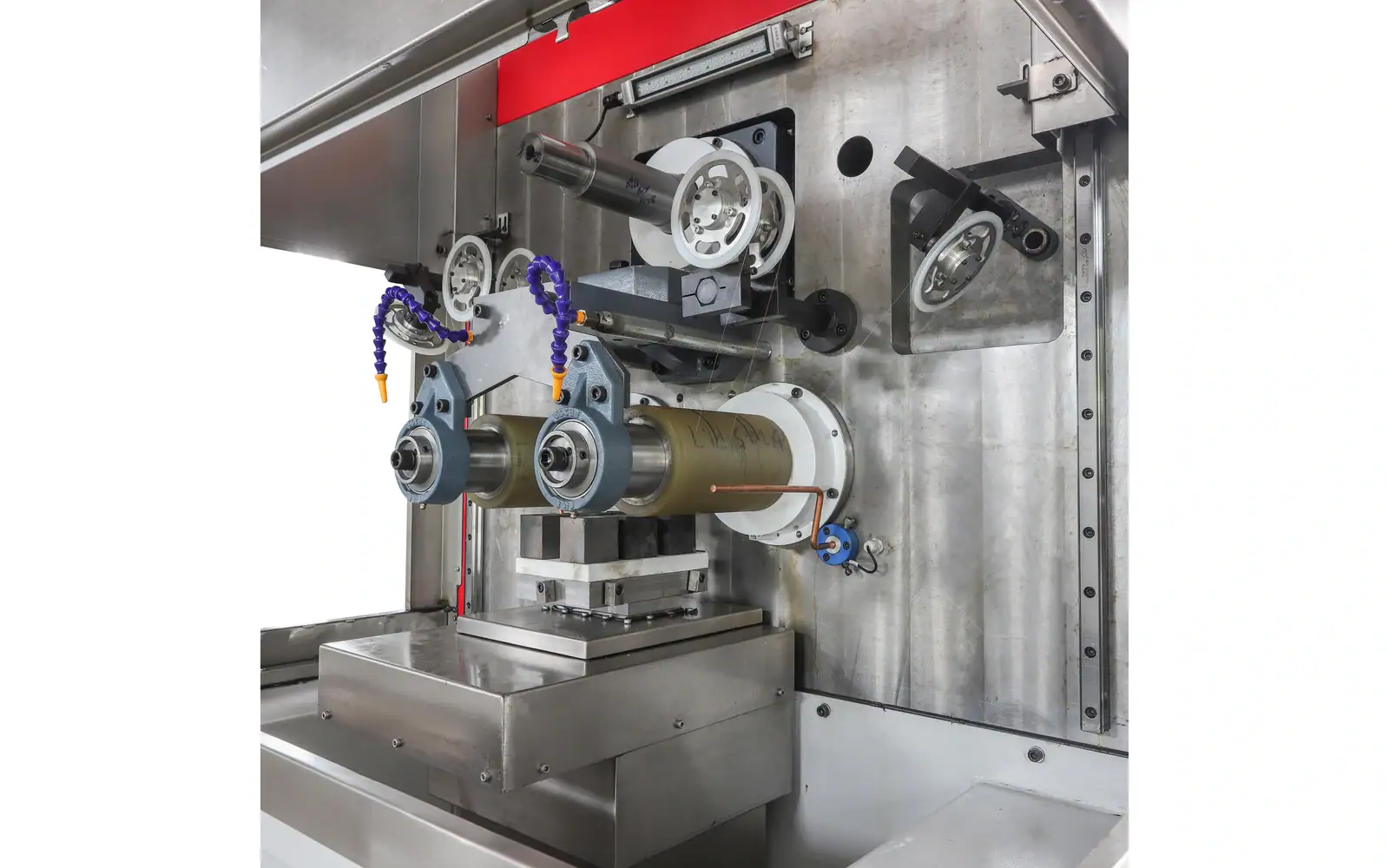
Vimfun SOMI-430 is the equipment reference mapped to this solar wafer slicing discussion. Its catalogue configuration must be checked against the specific photovoltaic stock and receiver; it is not a current solar-wafer thickness recommendation.
Compare Solar Wafer Slicing by the Required Output
The first question is what the blank must become. A photovoltaic manufacturing route and an electronic substrate route have different functions. Obtain the material specification and drawing for each instead of using “silicon wafer” as a complete description.
Le SEMI PV71 measurement scope addresses thickness and variation for photovoltaic applications. It illustrates the need for an application-specific inspection method, not a universal acceptance limit across every kind of silicon substrate.
Material Identification Comes before the Machine
Specify the crystal form, grade information and lot traceability available from the material supplier. Do not infer electrical or crystal properties from outside shape. A square piece is not sufficient evidence of solar-grade material, and a round ingot does not prove that it meets an electronic-grade specification.
Solar wafer slicing trials should use stock representative of the planned route. If the sample was selected from a different grade or a cleaner section, state that limitation. The result may still be useful for a mechanical question without proving suitability for the final application.
For comparison with electronic substrate production, the tranchage de lingots de silicium page provides the application boundary. Keep the material acceptance separate from the saw's geometric acceptance.
Shape Changes the Workholding Question
The stock's cross-section, usable length and reference surfaces determine how it can be mounted. Cropping or squaring may prepare a useful geometry for the intended route, but the required shape should come from the product plan rather than a habit carried over from another application.
A solar wafer slicing request should show the complete mounted assembly. Include the surface available for attachment and any parts excluded from use. A machine envelope that accommodates the bare block may still need fixture review.
Compare support throughout entry, the main cut and separation. Contact geometry changes during the cycle, and a setup that works for one shape may not reproduce the same behaviour with another.
Which thickness does the receiving process need?
Thickness is determined by the receiving process and handling route. Do not put a historical industry average into a new equipment specification without checking the applicable product. Thinness by itself does not describe uniformity, strength or finishing suitability.
For solar wafer slicing, count accepted blanks after the defined release and inspection steps. A nominally thin slice that breaks during transfer is not useful output. For semiconductor blanks, include the stock needed by the approved finishing route.
Un Scie multi-fils inversée is one equipment configuration for review. Its suitability for a particular wafer thickness must be evaluated against the actual material, mounted geometry and acceptance requirements.
SEMI PV71 describes an inline noncontact thickness and TTV method for clean, dry photovoltaic silicon wafers under its specified support arrangement. SEMI M1 concerns specified polished single-crystal wafers. Neither scope should be silently substituted for the other, and neither assigns your saw an acceptance result.
The SOMI-430 information lists a 430 × 160 × 150 mm workpiece envelope and a 0.3–3 mm slice range. Those machine references are not a current solar-wafer thickness recommendation. A solar wafer slicing enquiry outside an assessed configuration needs direct feasibility review rather than an assumed extension of that range.
I'd keep two separate acceptance sheets when comparing the routes. The trap is reporting the same nominal slice count while one trial includes finishing stock and the other does not. Solar wafer slicing recovery can only be interpreted when its actual blank and measurement condition are stated.
Count the same product.
Use an Application-Specific Damage Assessment
Surface appearance and subsurface condition are different inspection questions. Research on diamond-wire-sawn solar silicon investigates how cutting behaviour affects subsurface damage. It does not establish one damage depth or one operating recipe for all equipment.
Solar wafer slicing should therefore be assessed with the receiving team's relevant methods. Define whether the concern is edge chipping, cracks, surface condition or a later process result. State what the supplier can measure and what must be evaluated elsewhere.
Do not compare a visually inspected solar sample with an extensively measured semiconductor sample and call their yields equivalent. The acceptance effort and criteria need to be visible.
Are the two yields counting the same product?
Material recovery includes cutting width, end allowances, rejected slices and subsequent removal. Geometric yield and accepted finished yield are not the same result. State which quantity is reported and at what process stage.
In solar wafer slicing, a change in wire configuration might alter cutting width, output and handling demand simultaneously. Record all three rather than attributing the final result to only one variable. The same discipline applies to an electronic substrate trial.
A fair comparison keeps the starting usable section and acceptance criteria consistent. If a different stock length or finish allowance is necessary, identify the difference and explain how it affects the calculation.
Handling Can Decide Whether Thin Output Is Usable
Provide carriers and a release plan before cutting. Track where breakage appears: at separation, during debonding, in cleaning or during transfer. Without that timing, the process team may try to correct the saw for a problem introduced later.
Solar wafer slicing at a desired thickness does not establish that an existing handling system can process the blanks. Test the interface with the next operation using representative material. Keep the trial's packaging and transport condition recorded.
For a comparison project, return samples from multiple positions rather than only the best-looking pieces. Retaining order helps investigate a trend and reveals whether the trial demonstrated a stable batch or selected successful output.
Does the cycle include release and inspection?
Cutting time is only one part of a production cycle. Setup, mounting, release, cleaning, inspection, interruptions and finishing can all affect the usable output rate. State which operations are included in the quoted throughput.
Compare solar wafer slicing and semiconductor production using the intended batch and required output condition. A higher number of separated pieces does not demonstrate a higher number of accepted substrates if rejection or finishing demand differs.
Where data are incomplete, request a trial aimed at the missing interface. For example, a successful cut may justify a release study before a continuous-production assessment. Each test should resolve a specific uncertainty.
Compare the Two Receiving Operations Explicitly
Prepare one acceptance sheet for each route before comparing the machines. Identify the stock form, blank target, release condition and receiving operation. Two sheets may share fields, but their entries need not be identical. Keeping them separate prevents a capacity figure for one product from being interpreted as capacity for the other.
Solar wafer slicing comparisons should name where output is counted. A count at the saw and a count after handling or inspection describe different boundaries. Report both if they matter, with the corresponding batch identities. The lower count does not explain its own cause; retain rejection reasons and the stage at which they were observed.
Do not replace the actual product drawing with a general market trend. A statement that an industry favours thinner material does not tell an operator what this receiving process can use. Use the approved target and its inspection state, and keep any developmental target explicitly separate.
The route comparison should include the workpiece shape. Ask how each prepared section is mounted, what remains attached at the end and how slices are transferred. A layout that is efficient for one shape may not represent the other task. Compare the proposed assemblies rather than a headline maximum workpiece size.
For solar wafer slicing, define what the reported cycle includes. Setup, tool preparation, cutting, release and inspection may be reported separately. Neither grouping is inherently wrong, but it must be consistent when comparing equipment or planning the receiving operation.
Inspect the same status of material in both routes. If one report contains corrected samples and the other contains as-cut samples, the surface and thickness results are not a like-for-like comparison. Ask for the correction history and retain its place in the process record.
The next step is to identify the limiting handoff for the actual job. It might be the required blank condition, the release arrangement or the inspection capacity. A common wire mechanism does not establish that the two complete routes share the same useful throughput, even when the saw can physically accommodate both workpieces.
| Champ de décision | Preuves à conserver |
|---|---|
| Product boundary | PV or substrate receiver and target condition |
| Capacity boundary | Operations included in cycle and output count |
| Evidence boundary | As-cut/corrected samples and rejection stage |
Choisissez la page qui répond à votre question
This article answers: Are quoted capacities delivering the same accepted product? It does not replace the following equipment or application scopes.
| Votre question | Page pertinente | Limite |
|---|---|---|
| Besoin du contexte de la découpe de lingots de silicium ? | tranchage de lingots de silicium | Contexte d'application ou de processus pour la tâche de réception |
| Besoin du contexte de la scie à fil inversée ? | Scie multi-fils inversée | Configuration de l'équipement et sa portée déclarée |
FAQ
Can a substrate trial qualify solar wafer slicing capacity?
Not without matching the actual input and receiving requirements. Solar wafer slicing needs its own accepted-output definition. A machine result from another blank thickness, geometry or inspection boundary is an equipment reference, not a photovoltaic production guarantee.
Is slice count sufficient for solar wafer slicing comparison?
That is one useful count, but include the pieces that survive the agreed release and inspection steps. State the cycle boundary and distinguish separated output from accepted output. Otherwise the quoted capacities can describe different stages.
Does a machine range define the solar wafer slicing target?
No. Use the receiver’s drawing and approved inspection condition. A range describes an equipment configuration; it does not prescribe the current solar wafer specification or establish qualified performance at every point within that range.
Build Two Acceptance Sheets before Comparing Routes
For each route, list material identity, input shape, blank thickness, orientation if relevant, finishing allowance and inspection method. Add handling requirements and the acceptance stage at which output is counted. Then mark which requirements are shared and which are different.
Use those sheets to evaluate equipment, tooling and fixture options. Avoid importing numerical settings from an unrelated application; the operating window needs the actual material and machine procedure.
Prepare one acceptance sheet for each route with grade, stock shape, blank thickness, finishing allowance and inspection state. Identify the requirements that truly match. Compare solar wafer slicing only at a declared output boundary, including release losses and downstream rejection, before using a throughput figure to justify a machine choice.