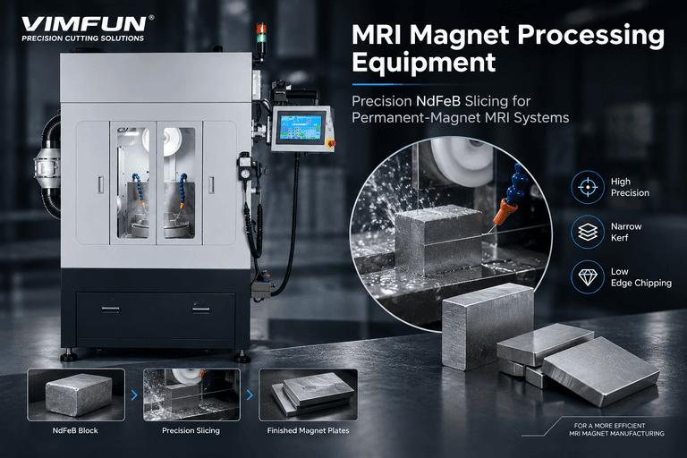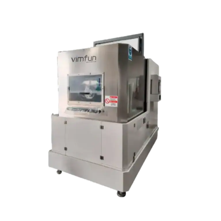
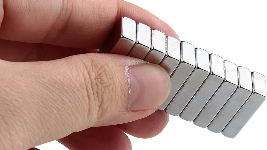
В ветрогенераторах с прямым приводом вместо редукторов используются генераторы на постоянных магнитах. Каждый генератор содержит 600–2000 кг магнитов NdFeB, расположенных в виде десятков больших сегментов дугообразной формы, прикрепленных болтами к ротору. Эти сегменты значительно крупнее и толще магнитов, используемых в двигателях электромобилей или потребительской электронике, что создает особые проблемы для станка для резки магнитов ветрогенераторов, используемого для их производства.
Сайт сектор ветроэнергетики в 2024 году потребил примерно 7000–9000 тонн магнитов NdFeB, и это число растет, поскольку все больше производителей турбин внедряют конструкции с прямым приводом. Если вы поставляете магниты на этот рынок, ваше режущее оборудование должно соответствовать размерам блоков, допускам и требованиям к производительности, для которых стандартные станки для нарезки магнитов не были разработаны.
Почему магниты для ветрогенераторов требуют специализированного режущего оборудования
Большие размеры блоков
Типичный магнит двигателя электромобиля сегмент имеет размеры 30–50 мм в самом длинном измерении. Сегменты магнитов ветрогенераторов обычно достигают 80–150 мм в длину и 20–40 мм в толщину. Некоторые конструкции генераторов с прямым приводом используют сегменты длиной до 200 мм.
Это означает, что станок для резки магнитов ветрогенераторов должен иметь:
- Рабочую зону, вмещающую блоки с поперечным сечением до 200 мм × 200 мм
- Достаточную длину хода проволоки или лезвия для выполнения резки по всей глубине блока
- Системы крепления, которые жестко удерживают большие блоки без образования трещин от напряжения
Более толстая резка, более жесткие допуски
Сегменты магнитов ветрогенераторов толще магнитов электромобилей, но требования к допускам столь же строги. Воздушный зазор между магнитами ротора и статором в генераторе с прямым приводом имеет решающее значение для выходной мощности — обычно требуется допуск по толщине магнита ±0,1 мм для сегментов толщиной 20–40 мм.
Поддержание ±0,1 мм при толщине 40 мм сложнее, чем поддержание того же допуска при толщине 5 мм для нарезки магнитов электромобилей. Отклонение проволоки, тепловое расширение и крепление блока становятся более критичными по мере увеличения толщины сечения.
Давление стоимости материалов
Стоимость сырья NdFeB составляет $80–$120/кг в зависимости от марки и рыночных условий на редкоземельные металлы. Один генератор ветровой турбины содержит магниты NdFeB стоимостью $50 000–$200 000. Каждый миллиметр потерь на пропил при резке напрямую снижает выход и увеличивает стоимость на турбину.
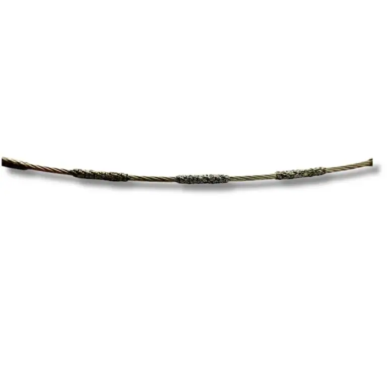
Это делает ширину пропила одной из самых важных характеристик любой машины для резки магнитов ветровых турбин. Разница между пропилом шириной 2 мм (традиционное лезвие) и пропилом шириной 0,5 мм (алмазный провод), умноженная на сотни резов на генератор, приводит к экономии материалов в тысячи долларов.
Машина для резки магнитов ветровых турбин: Ключевые требования
Сравнение методов резки магнитов ветровых турбин
| Технические характеристики | Алмазная проволочная пила | Многопильный станок | Однопильный станок |
|---|---|---|---|
| Ширина реза | 0,3–0,6 мм | 1,5–2,5 мм | 2,0–3,0 мм |
| Максимальный размер блока | До 200 мм | До 150 мм | До 300 мм |
| Шероховатость поверхности (Ra) | 0,8–2,0 мкм | 1,5–4,0 мкм | 2,0–6,0 мкм |
| Контурная резка | ✅ Путь ЧПУ | ❌ Только прямая | ❌ Только прямая |
| Сколы по краю | < 0,1 мм | 0,2–0,5 мм | 0,3–0,8 мм |
| Использование материала | 90–95% | 75–85% | 70–80% |
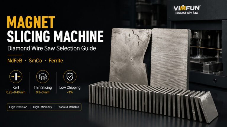
Алмазная резка проволокой предлагает наилучшее сочетание узкого пропила, качества поверхности и геометрической гибкости. Для магнитов ветряных турбин, в частности, ценна возможность контурной резки — дугообразные сегменты генератора можно вырезать непосредственно из блока, а не вырезать прямоугольные детали и шлифовать их до нужной формы.
Критические характеристики машины
При оценке станка для резки магнитов ветрогенераторов наиболее важны следующие характеристики:
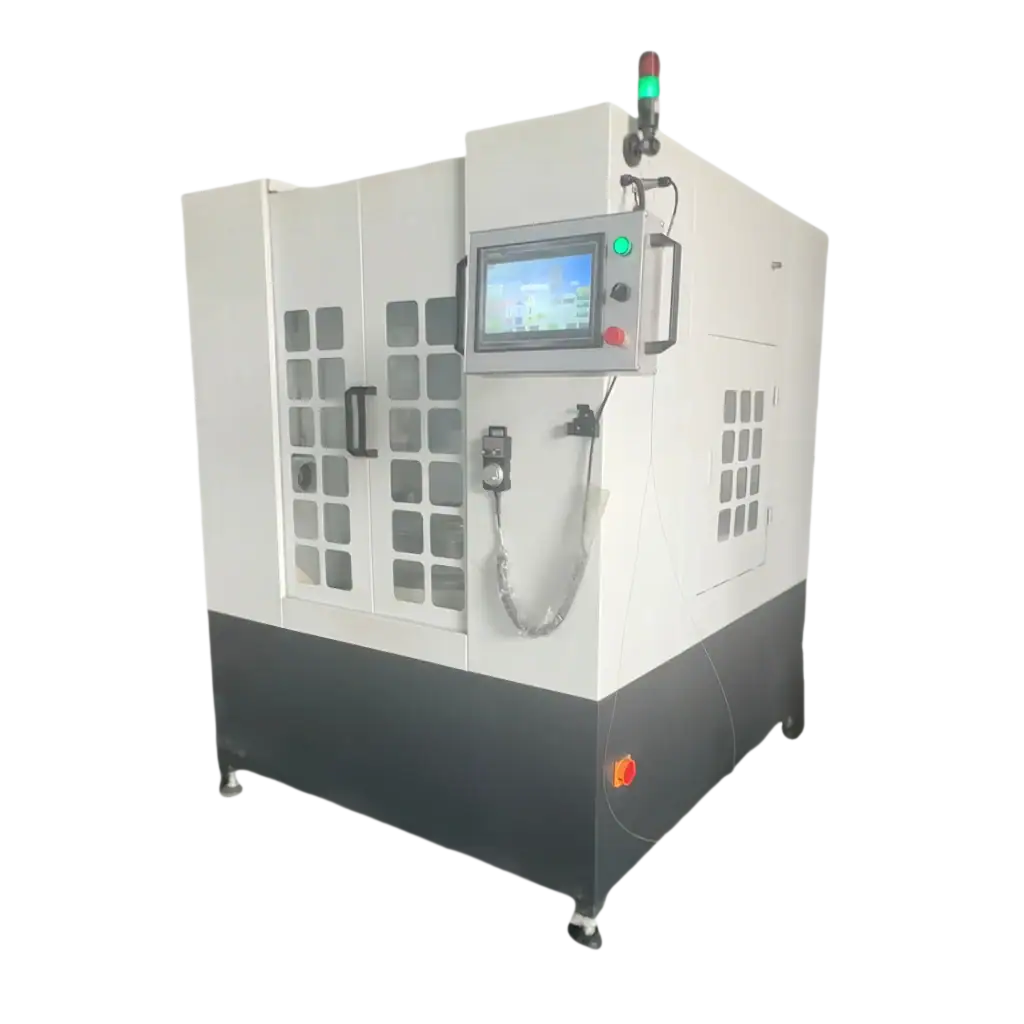
Рабочая зона. Должна вмещать ваш самый большой размер блока с местом для крепления. Для производства магнитов ветрогенераторов минимальная мощность Φ185 мм × 400 мм охватывает большинство геометрий сегментов генератора.
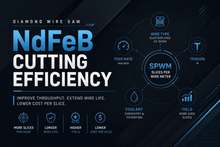
Контроль натяжения проволоки. Сервоуправляемое натяжение (диапазон 80–200 Н) необходимо для поддержания точности резки толстых блоков NdFeB. Ручная регулировка натяжения не может компенсировать тепловые и механические изменения, происходящие во время 30–60-минутной резки большого блока.
Система охлаждения. При резке NdFeB образуются мелкие магнитные частицы, которые должны непрерывно вымываться из зоны резки. Система охлаждения нуждается в магнитном сепараторе для удаления стружки NdFeB — стандартные отстойники недостаточны, поскольку магнитные частицы слипаются и рециркулируют. Водно-дисперсионный хладагент с ингибиторами коррозии является стандартом для обработки NdFeB.
Контроль скорости подачи. Адаптивный контроль подачи, реагирующий на сопротивление резки, важен для больших блоков. Плотность и структура зерна NdFeB могут варьироваться в пределах одного блока, особенно в более крупных спеченных блоках. Постоянная скорость подачи через зону с более высокой плотностью вызывает отклонение проволоки и изменение толщины.
Рабочий процесс производства магнитов ветрогенераторов
Станок для резки обрабатывает этапы 2 и 3 в типичном производственном процессе магнитов ветрогенераторов:
| Этап | Процесс | Оборудование | Назначение |
|---|---|---|---|
| 1 | Спекание блоков | Печь для спекания + пресс | Порошок NdFeB → спеченный блок |
| 2 | Контурная резка | Станок для резки магнитов ветрогенераторов | Блок → грубые сегменты |
| 3 | Резка по толщине | Станок для резки магнитов ветрогенераторов | Черновые заготовки → конечная толщина |
| 4 | Шлифовка поверхности | Двусторонняя притирка/шлифовка | Достижение конечного допуска ±0.1 мм |
| 5 | Обработка поверхности | Линия нанесения покрытия (NiCuNi / эпоксидная смола) | Защита от коррозии |
| 6 | Намагничивание | Импульсный намагничиватель | Выравнивание магнитных доменов |
| 7 | Инспекция | Гауссметр + КИМ | Проверка магнитных и размерных характеристик |
Одна проволочная пила может выполнять как контурную резку, так и резку по толщине путем изменения программы резки. Это сокращает количество оборудования и занимаемую площадь по сравнению с использованием отдельных станков для каждой операции.
Экономия материала: Экономика станка для резки магнитов ветряных турбин
Экономическое обоснование станка для резки магнитов ветряных турбин с узким пропилом очевидно:
| Сценарий | Пила для лопастей (пропил 2,0 мм) | Проволочная пила (рез 0,5 мм) |
|---|---|---|
| Резы на генератор (пример) | 200 | 200 |
| Материал, потерянный за рез | 2,0 мм × площадь реза | 0,5 мм × площадь реза |
| Общие потери на рез на генератор | ~3 кг NdFeB | ~0,75 кг NdFeB |
| Стоимость материала, потерянного на рез | $240–$360 | $60–$90 |
| Экономия на генератор | — | $180–$270 |
| Годовая экономия (100 генераторов) | — | $18,000–$27,000 |
Эти цифры не включают дополнительную экономию от более высокого использования материала (требуется меньше шлифовального материала) и меньшего скола кромок (меньше отбракованных деталей при проверке).
При обработке магнитов для нескольких производителей турбин кумулятивная экономия покрывает инвестиции в оборудование в течение 12–18 месяцев.
Выбор правильной машины для резки магнитов ветряных турбин
Для новых линий производства магнитов: Начните с алмазно-проволочной пилы, которая выполняет как контурную резку, так и распиловку. Одна машина с программированием траектории ЧПУ подходит для большинства геометрических форм магнитов ветряных турбин. Только меньшие потери на пропил оправдывают инвестиции по сравнению с альтернативами на основе лезвий.
Для существующих линий, увеличивающих мощность: Если ваши текущие пилы с лезвиями создают чрезмерные потери на пропил или не могут обеспечить качество поверхности, которое требуют ваши клиенты, модернизация проволочной пилы на этапе резки обеспечивает быструю окупаемость инвестиций. Последующие этапы шлифовки и финишной обработки становятся короче, когда режущая поверхность изначально чище.
Для заводов по производству магнитов различного назначения: Если вы производите как магниты для ветряных турбин, так и меньшие магниты для электродвигателей электромобилей, ищите машину с достаточным рабочим пространством для ваших самых больших блоков магнитов для ветряных турбин, которая при этом обеспечивает точность для резки более тонких пластин магнитов для электромобилей. Машина, рассчитанная на блоки диаметром Φ185 мм с точностью позиционирования ±0,03 мм, подходит для обоих применений.
Для получения дополнительной информации о том, как технология алмазной проволоки применяется к обработка редкоземельных магнитов, включая различные марки и геометрии магнитов, ознакомьтесь с нашим обзором. Вы также можете изучить конкретные шлифовальная машина для дуговых магнитов используемые в последующей обработке изогнутых сегментов магнитов ветряных турбин.